
Control electrical devices with a Relay and the ESP32 with Arduino code
(Updated at 01/09/2023)
If you want to do home automation, the relay is the essential module. Indeed, coupled with an ESP32, you can directly control household appliances on your phone, your computer, or anywhere in the world from the Internet if you wish.
Warning
Handling line voltages are dangerous. If you have to use them, it must be done with the utmost caution. For permanent use, I strongly advise you to use good quality professional relay modules and to have your installation checked by a professional before any use.
Getting started with a Relay
A relay is very easy to use, primarily when they are sold in the form of a module that contains an elementary circuit to use it.
Note
I strongly encourage you to take a ready-made module that integrates the relay with its minimal circuit rather than using the relay alone and making the circuit for the logic part yourself (the relay itself does not fit on a breadboard and should not be put on it anyway).
Presentation and functioning of a Relay
Suppose you have never used a relay before or are curious to understand how it works, its use cases and its limitations. In that case, you should consult a:ref:` more theoretical article on how a relay works <8ae9b35e6bf743569833746474be4657>` .
Very briefly, it’s a mechanical switch that you control via the ESP32 to turn on/off a strong DC electrical circuit (RGB led strips, pumps) or a device connected to the 220V mains (fans, lights, heater, motor…).
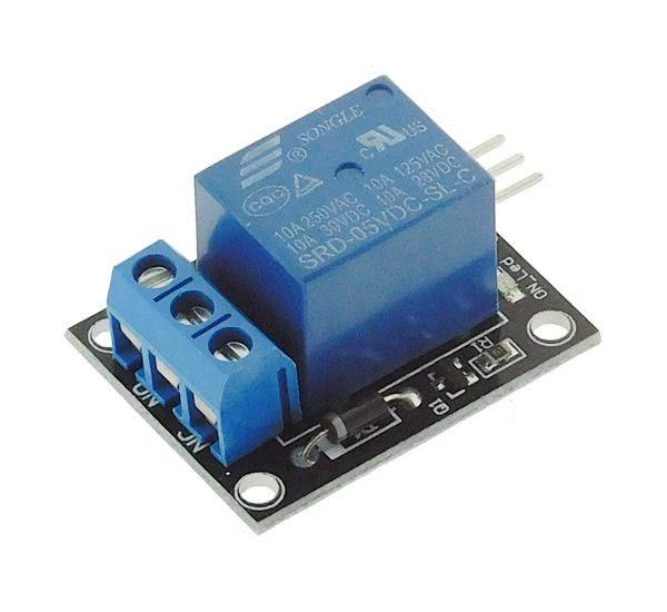
Connection of the SRD-05VDC-SL-C Relay
In most Arduino kits, the modules use the SRD-05VDC-SL-C from the manufacturer Songle . Generally, they come in 2 categories: a module with a single relay and another with several relays simultaneously. So if you plan to drive several power circuits separately in one project, it is more interesting to take a multi-relay module.
Note
This relay is made to be powered in 5V: SRD-05VDC -SL-C. If you use an ESP32 on a LiPo battery, the available voltage will be between 3.3V and 4.2V. In this case, it would be wise to take a module SRD-03VDC -SL-C powered by 3.3V.
Warning
Contrary to the diagram with a transistor, the ground of the logic part and the power part is completely separated. You must not connect them, especially if it is 220V AC or there is no ground!
On the model SRD-05VDC-SL-C, there are three pins to drive the relay:
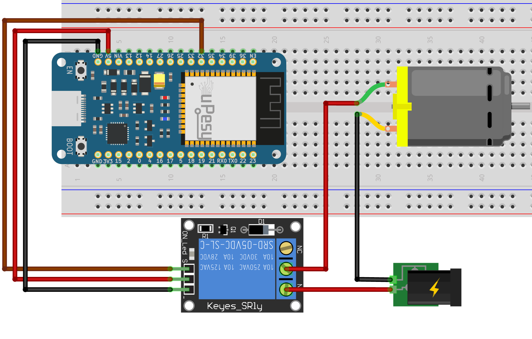
The pin
S, on the left, is connected to a pin of the ESP32 (hereGPIO32). It allows sending a signal to drive the relay.The middle pin is the power supply connected to the 5V of the ESP32 (3V3 if it is the SRD- module 03VDC -SL-C).
The last pin, represented by
-, is the ground connected to a pinGND.
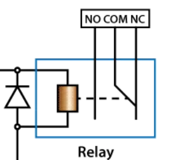
The relay has a 3-pin terminal block on the power side:
NC→ Normally Closed contact.COM→ the middle pin is called common (COM).NO→ Normally Open: Normally Open contact.
The device in the circuit will be connected to the terminal COM and NO or NC depending on your application. By choosing NO , the relay will be open by default (the electrical circuit will not be closed). The circuit will be closed only when a signal is sent to the relay.
On the other hand, by choosing the terminals COM and NC , the circuit will be closed by default (when the relay is not activated): the device is switched on. When the relay is activated, the circuit will open, and the connected device will no longer be powered.
Choosing the least dangerous mode is safer in case of a control failure (or if the relay is out of service). For example, if it is to supply a heating resistor, it is better to have the circuit open if the relay does not work correctly anymore.
Note
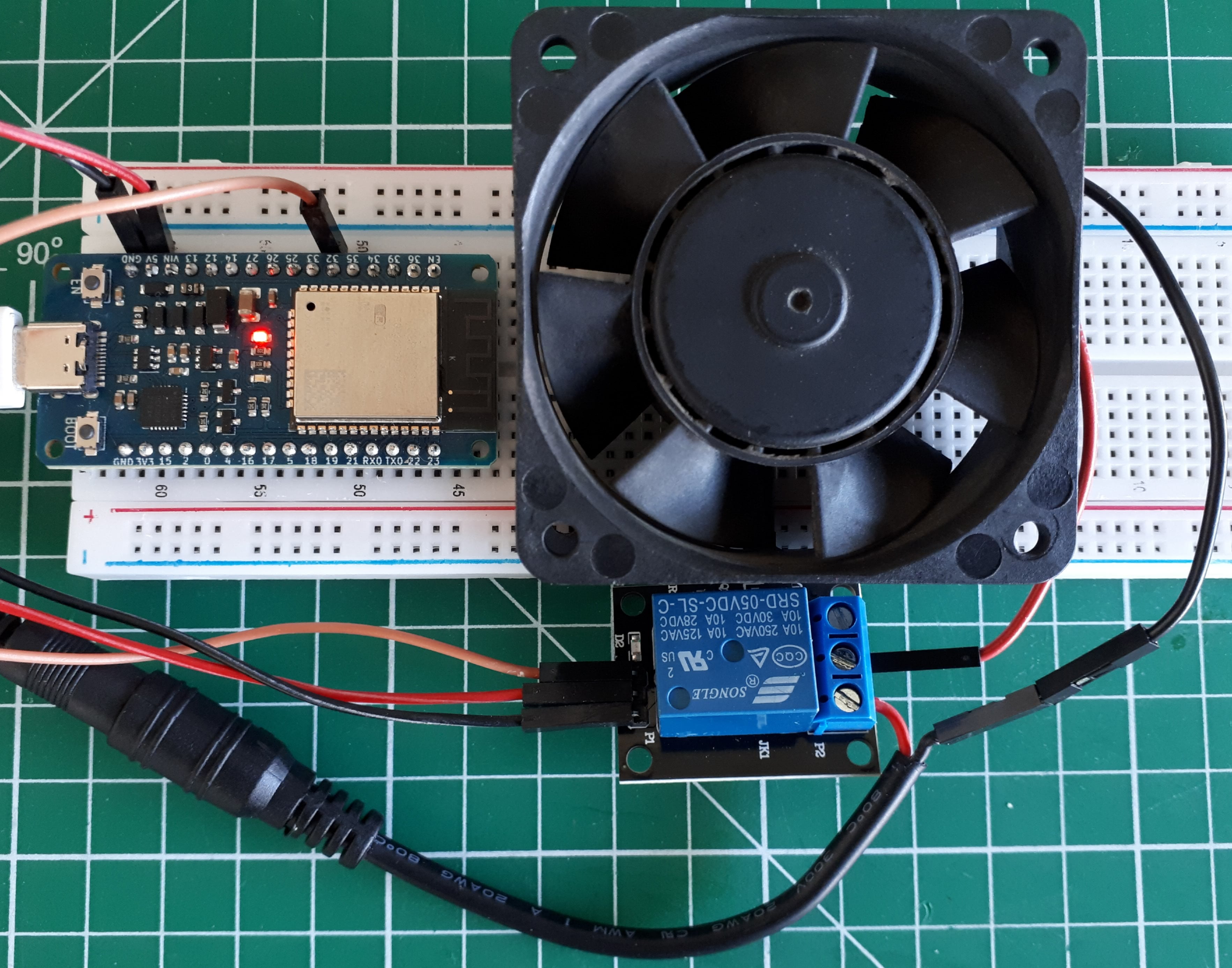
I recommend you to use the combination COM and NO if it is to turn on a device (lamp, motor, pump).
Here is an example of a relay that turns on a large computer fan:
Control the Relay with Arduino code on the ESP32
For the time being, the Arduino code is straightforward; it’s like turning on and off an LED. The code is identical to the famous sketch blink . There is no need to install third-party libraries.
#define RELAIS 32

void setup() {
  pinMode(RELAIS,OUTPUT);
}

void loop() {
  digitalWrite(RELAIS, HIGH); // The circuit is closed for 200ms
  delay(200);
  digitalWrite(RELAIS,LOW); // The circuit is open for 5s
  delay(5000);
}
Note
The relay is controlled in all or nothing (0V or 5V) and not with a variable voltage PWM signal.
And here is what it gives with the proposed circuit:
Note
A transistor circuit would be more appropriate to switch a motor on/off very frequently.
Des modules relais avancés multicanaux
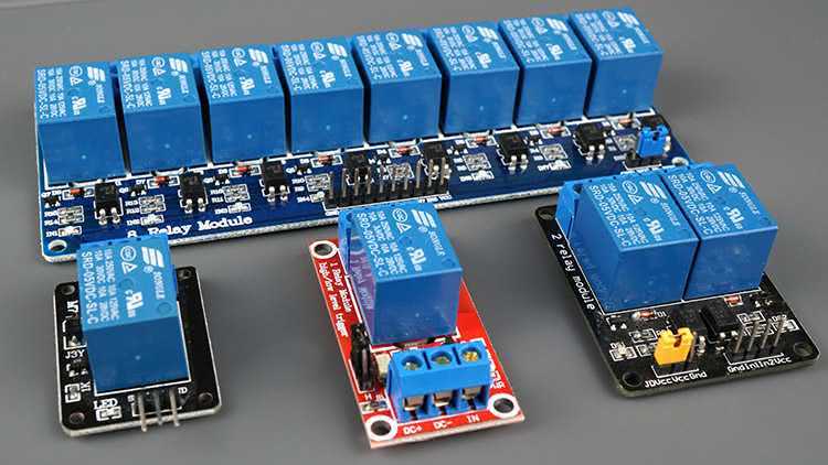
There are a variety of relay modules available, ranging from 1 to 8 channels. For a home automation system, this is very convenient. Each of them can control a corresponding number of outputs. They usually use the same blue SRD-05VDC-SL-C relay.
Separate the ESP32 from the Relay with the Optocouplers
There is usually a built-in optocoupler on models with fewer channels to isolate the relay from your ESP32.
Note
An optocoupler completely isolates a logic signal with a light-sensitive transmitter and receiver.
For this protection layer to be beneficial, the relay circuit must be powered by an external 5V voltage source on the pin JD-VCC . You will notice that on these models, there are usually additional pins with a jumper JD-VCC , VCC and GND .
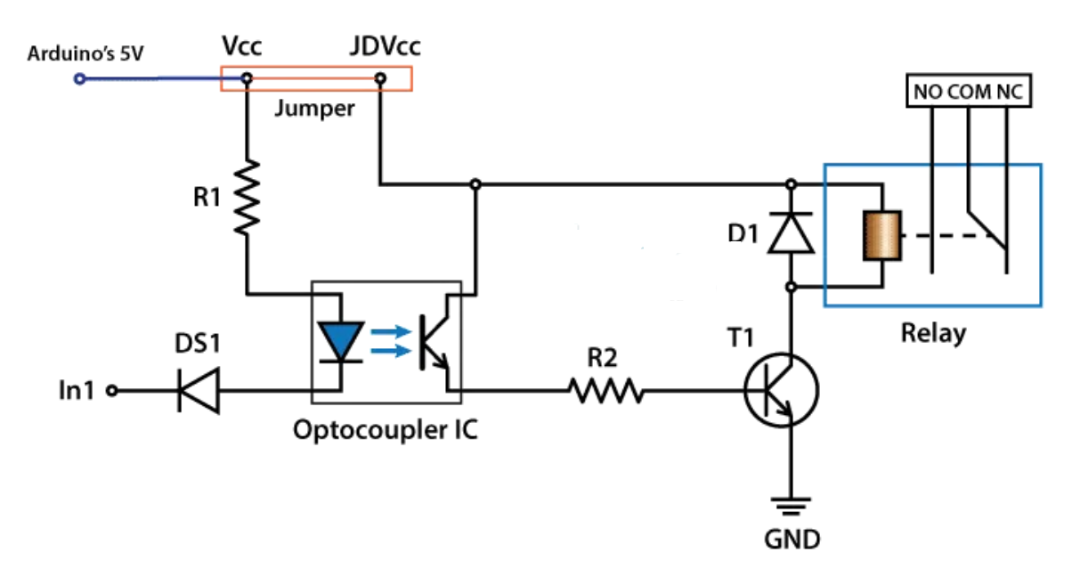
By leaving the jumper, the optocoupler is no longer helpful.😕 It can be useful to use an external power supply, not coming from the ESP32, if the relays consume too much current to power the electromagnet (if there is an 8 on a module, for example).
Note
In practice, the jumper is set to the correct configuration by default; you can leave it like that.
Use multi-channel Relay modules
The operation is the same as with a single module. There are just several pins, VIN VIN1 , VIN2 , and VIN3 … to control the relays independently.
#define RELAIS_0 32
#define RELAIS_1 33

void setup() {
  pinMode(RELAIS_0 ,OUTPUT);
    pinMode(RELAIS_1 ,OUTPUT);
}

void loop() {
  digitalWrite(RELAIS_0 , HIGH); // Relay 0 is activated for 5s
  digitalWrite(RELAIS_1 , HIGH); // Relay 1 is activated for 5s
  delay(5000);
  digitalWrite(RELAIS_0 ,LOW); // Relay 0 is deactivated for 5s
  digitalWrite(RELAIS_1 ,LOW); // Relay 1 is deactivated for 5s
  delay(5000);
}
Warning
I’ll say it again, but for permanent use, get an excellent quality relay module from a reliable manufacturer (with regulatory certification) and not the cheapest available on Aliexpress. 😉