Create analog voltage on ESP32 with PWM
(Updated at 12/23/2022)
The PWM (Pulse With Modulation) artificially creates a variable voltage between 0 and 3.3V. The PWM on the ESP32 is much more complete than on the Arduino.
A reminder of the PWM working principle
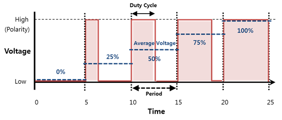
PWM is a method for obtaining analog-looking signals on digital pins. We create a square wave, a signal switching between a HIGH and LOW level, between 0V and 3.3V. This succession of HIGH / LOW levels can simulate an intermediate voltage between the two levels by playing on the balance when the signal is HIGH and LOW. The duration of the HIGH level is called the “duty cycle.” You must change or modify this pulse width to obtain an analog variation.
Note
The signal frequency is fixed, and we can change only the duty cycle.
PWM usage on ESP32 with Arduino code
Using PWM on the ESP32 is different from using the Arduino. Sixteen independent PWM channels can be assigned to GPIO pins (except GPIO36, GPIO39, GPIO34, and GPIO35 pins). The PWM configuration is a bit more complex on the ESP32 but is more powerful. The ledc module takes care of the PWM, and three primary functions will allow it to be used: ledcSetup() , ledcAttachPin() , ledcWrite()
To generate a PWM signal, for example, on pin GPIO23, you must:
Choose a PWM channel (0 - 15)
Choose the PWM frequency
Choose the resolution of the pulse width between 1 and 16 bits
Choose the GPIO pin which will generate the PWM signal
Assign the value of the voltage you want at the output
int pwmChannel = 0; // Selects channel 0
int frequence = 1000; // PWM frequency of 1 KHz
int resolution = 8; // 8-bit resolution, 256 possible values
int pwmPin = 23;

void setup(){
    // Configuration of channel 0 with the chosen frequency and resolution
    ledcSetup(pwmChannel, frequence, resolution);

    // Assigns the PWM channel to pin 23
    ledcAttachPin(pwmPin, pwmChannel);

    // Create the selected output voltage
    ledcWrite(pwmChannel, 127); // 1.65 V
}

void loop(){
}
Once the configuration with the ledcSetup() and ledcAttachPin() functions is done, we only use the ledcWrite() function to set the voltage.
Warning
The analogWrite() function will not work on the ESP32. You should use ledcWrite() instead.
Mini-Project: Dimming LEDs via PWM
We will dim three LEDs with a PWM signal.
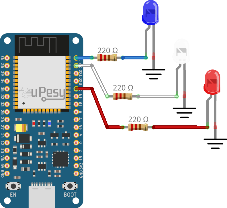
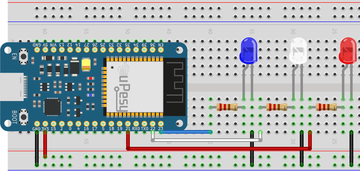
Electrical schematic
Choose the colors of LEDs that you want.
Warning
Don’t forget to put resistors in series with the LEDs to avoid burning them out. A value between 220Ω and 330Ω will do the job nicely.
Code to control the brightness of the LEDs
Solution
const int ledPin = 23;
const int ledPin2 = 22;
const int ledPin3 = 21;

// PWM channel 0 parameter
const int freq = 5000; // 5000 Hz
const int ledChannel = 0;
const int resolution = 8; // 8-bit resolution

void setup(){
    // Configure the channel 0
    ledcSetup(ledChannel, freq, resolution);

    // Attach the channel 0 on the 3 pins
    ledcAttachPin(ledPin, ledChannel);
    ledcAttachPin(ledPin2, ledChannel);
    ledcAttachPin(ledPin3, ledChannel);
}

void loop(){
    // Increase the brightness of the led in the loop
    for(int dutyCycle = 0; dutyCycle <= 255; dutyCycle++){
        ledcWrite(ledChannel, dutyCycle);
        delay(15);
    }
}
Instead of using three different PWM channels for each pin, only one is used and assigned to the three pins.
Results