
Using a rotary encoder with Arduino Code with an ESP32
(Updated at 01/20/2023)
Rotary encoders are position sensors that measure an axis’s angular position (or rotation). They’re mostly used in motors for PID control and user interfaces as an alternative to potentiometers. Furthermore, many encoders used in DIY kits have a push button built-in.
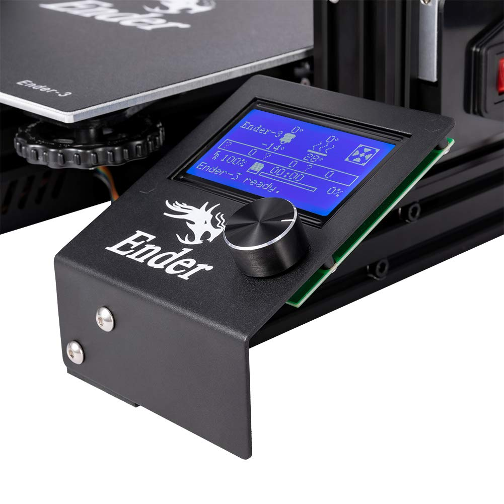
The control button on 3D printers is usually a rotary encoder
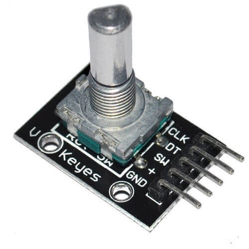
Getting started with a rotary encoder: the KY-040
This tutorial will explore utilizing a KY-040 rotary encoder module, a common component in DIY kits. We can use this module to create a user interface for our program; for example, to select options from a menu or change the value of a variable.
Difference between rotary encoder and potentiometer
At first, the rotary encoder KY-040 may look like a potentiometer. However, a potentiometer is an analog sensor while the rotary encoder is digital. A potentiometer changes the value of a resistor, but its range is limited.
A rotary encoder can detect a specific number of “steps” for each revolution and sends a signal at each step. It also can turn endlessly. You can physically feel the difference between the two; a potentiometer rotates smoothly, while a rotary encoder turns jerkily.
A rotary encoder is a device that can be easily used with a microcontroller, as it sends digital signals. The precision of the encoder is based on the number of steps per rotation. At the same time, the accuracy of a potentiometer is determined by the resolution of the ADC that is used to measure its position.
Note
A potentiometer is a device utilized to modify analog settings, such as the volume of an amplifier. In contrast, a rotary encoder is employed to get an angular direction and position accurately.
How works a rotary encoder?
This guide provides an overview of rotary encoders but does not dive into technical details.🤓 To gain a deeper understanding of the physical processes, different technologies, and classic topologies (such as the operation of an optical quadrature phase rotary encoder 😨), please refer to the theoretical presentation of a rotary encoder.
Connections of the KY-040 rotary encoder to the ESP32
This rotary encoder has 2 signals to know the position: CLK and DT . The pin SW is connected to the integrated push button (SWitch).
Warning
If you use a raw rotary encoder, not a breakout module, you must add pull-up resistors to the 3 logic pins. This is because these resistors must distinguish between the different logic levels as with the standard push-button circuit.
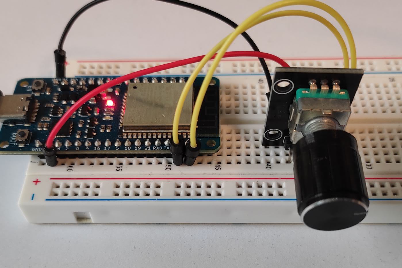
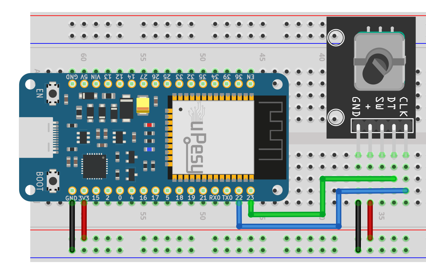
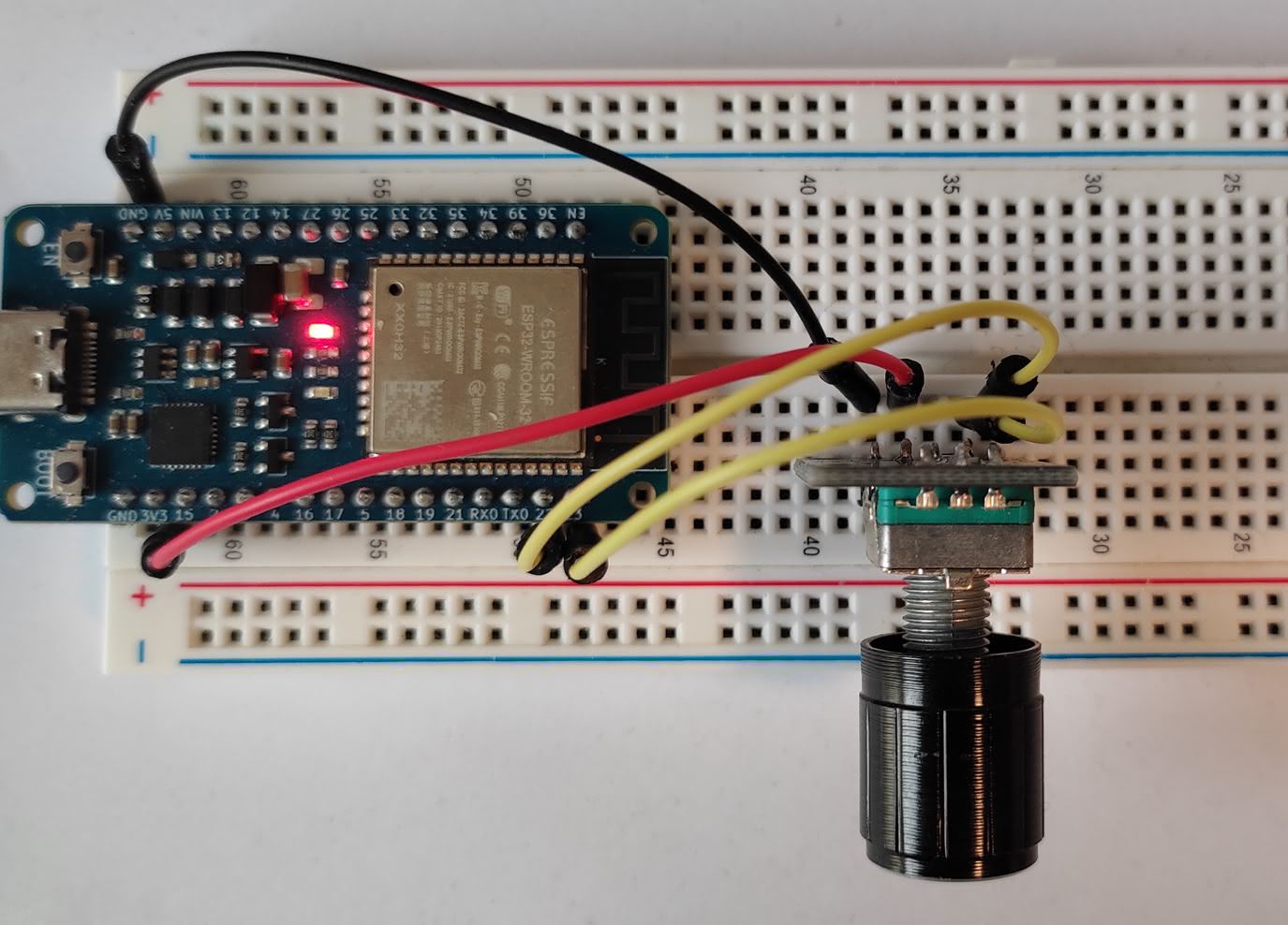
Here is a proposal for a connection to an ESP32 board :
Rotary Encoder |
ESP32 |
|---|---|
|
|
|
|
|
|
|
|
|
|
The circuit to be done is as follows:
And here is an example of breadboard mounting:
Get the angular position of the KY-040 rotary encoder in Arduino code
Incremental encoders are used to measure the angular position in degrees based on the number of increments made by the user. Instead of providing an exact angular position, this type of encoder returns the number of increments done. To get the angle, the value of the increment must be determined in the program.
Finding the amount of steps an encoder has made is possible through various methods. It is best to use a reliable way to get steps without blocking the program. A basic approach where a loop looks for logical signals received from the encoder carries the risk of missing steps if the encoder is rotated fast.
Note
Programs can sometimes struggle with tasks and count in the wrong direction. (A traditional bug)
Many code sources are available online if you want to use rotary encoders. However, not all of them are the same! The best choice is to trigger hardware interrupts when a logical level change is detected. These interrupts are independent of the CPU and won’t stop the code from running.
Note
The ESP32 can attach an interrupt to any output pins, which is impossible when using an Arduino, as only a few pins can have interrupts.
Some Arduino libraries compatible with the ESP32
It’s often better to use libraries rather than write your code. Two libraries that are well-suited for ESP32 are:
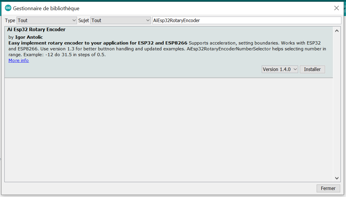
The AiEsp32RotaryEncoder library is an excellent choice for creating user interfaces, like menus, or for adjusting parameters. It utilizes hardware interrupts for incrementing calculations and is specifically adapted for rotary encoders with integrated push buttons, such as the KY-040 encoder.
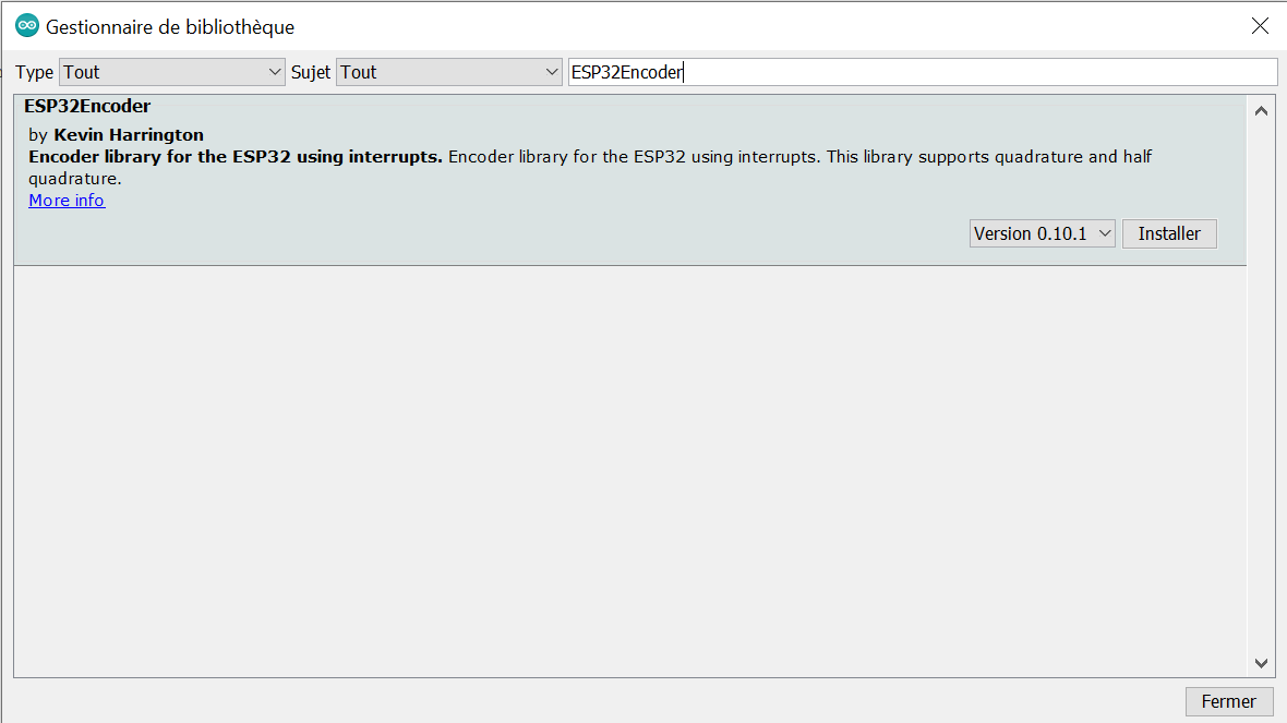
The ESP32Encoder library uses the PCNT peripheral on the ESP32 to perform counting operations. The advantage of this approach is that it doesn’t require any CPU processing, making it very performant. However, its functionality is limited compared to other libraries; there are no interrupts for each increment and no push button functionality. It is recommended to use this library when measuring encoder values from a motor, where there will be hundreds of increments per second. The current increment can be read easily at any time with the simple function provided by the library.
Note
The ESP32’s PCNT hardware controls up to 8 rotary encoders simultaneously.
The 2 libraries are easily installed from the Arduino IDE :
Use a rotary encoder for a user interface with the library AiEsp32RotaryEncoder
The library is installed from the library manager in the Arduino IDE.
Here is a skeleton code to show the possibilities of this library:
#include "AiEsp32RotaryEncoder.h"
#include "Arduino.h"

#define ROTARY_ENCODER_A_PIN 23
#define ROTARY_ENCODER_B_PIN 22
#define ROTARY_ENCODER_BUTTON_PIN 21
#define ROTARY_ENCODER_VCC_PIN -1
#define ROTARY_ENCODER_STEPS 4

//instead of changing here, rather change numbers above
AiEsp32RotaryEncoder rotaryEncoder = AiEsp32RotaryEncoder(ROTARY_ENCODER_A_PIN, ROTARY_ENCODER_B_PIN, ROTARY_ENCODER_BUTTON_PIN, ROTARY_ENCODER_VCC_PIN, ROTARY_ENCODER_STEPS);

void rotary_onButtonClick()
{
    static unsigned long lastTimePressed = 0; // Soft debouncing
    if (millis() - lastTimePressed < 500)
    {
            return;
    }
    lastTimePressed = millis();
    Serial.print("button pressed ");
    Serial.print(millis());
    Serial.println(" milliseconds after restart");
}

void rotary_loop()
{
    //dont print anything unless value changed
    if (rotaryEncoder.encoderChanged())
    {
            Serial.print("Value: ");
            Serial.println(rotaryEncoder.readEncoder());
    }
    if (rotaryEncoder.isEncoderButtonClicked())
    {
            rotary_onButtonClick();
    }
}

void IRAM_ATTR readEncoderISR()
{
    rotaryEncoder.readEncoder_ISR();
}

void setup()
{
    Serial.begin(115200);

    //we must initialize rotary encoder
    rotaryEncoder.begin();
    rotaryEncoder.setup(readEncoderISR);
    //set boundaries and if values should cycle or not
    //in this example we will set possible values between 0 and 1000;
    bool circleValues = false;
    rotaryEncoder.setBoundaries(0, 1000, circleValues); //minValue, maxValue, circleValues true|false (when max go to min and vice versa)

    /*Rotary acceleration introduced 25.2.2021.
   * in case range to select is huge, for example - select a value between 0 and 1000 and we want 785
   * without accelerateion you need long time to get to that number
   * Using acceleration, faster you turn, faster will the value raise.
   * For fine tuning slow down.
   */
    //rotaryEncoder.disableAcceleration(); //acceleration is now enabled by default - disable if you dont need it
    rotaryEncoder.setAcceleration(250); //or set the value - larger number = more accelearation; 0 or 1 means disabled acceleration
}

void loop()
{
    //in loop call your custom function which will process rotary encoder values
    rotary_loop();
    delay(50); //or do whatever you need to do...
}
This is what you get in the serial monitor when you turn the encoder:
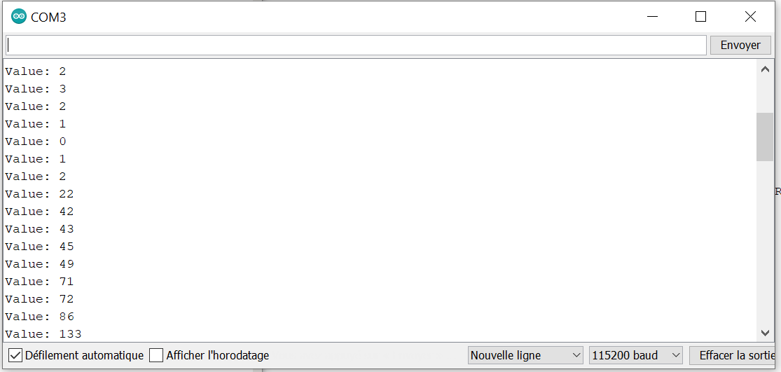
When you turn the encoder, the values don’t always increase linearly. That’s because the “Acceleration” mode is enabled, which increases the value quicker when you turn the encoder quickly. This is very helpful for adjusting a parameter that has huge values. If you want to turn off the acceleration mode, use the command rotaryEncoder.disableAcceleration() . You can also change the acceleration behavior with rotaryEncoder.setAcceleration(0-1000) .
This library can count in the background, even if you take the rotary_loop() out of the loop() . The code above can be used as a starting point for your project. To find out all the features this library has to offer, please visit the GitHub repository for the documentation.
Get the angular position of a rotary encoder using the ESP32 hardware counter (PCNT) with the lib ESP32Encoder
The library ESP32Encoder is installed directly from the Arduino IDE :
The code is much simpler than the previous library, but at the same time, you can only get the value of the encoder increment.
#include <ESP32Encoder.h>

#define CLK 22 // CLK ENCODER
#define DT 23 // DT ENCODER

ESP32Encoder encoder;

void setup () {
  encoder.attachHalfQuad(DT, CLK);
  encoder.setCount(0);
  Serial.begin ( 115200 );
}

void loop () {
  long newPosition = encoder.getCount();
  Serial.println(newPosition);
  delay(25);
}
The count will still be accurate even when a 500 ms interval is set in the loop() function since the counting is achieved by the PCNT hardware device. We can also get the value incrementing gradually through the serial terminal. getCount() is the function that retrieves the value from the hardware counter register, the one doing the counting.
Note
If you’ve missed some steps, you can use the setFilter() function to filter the signal input at the hardware counter (PCNT) as much as possible.
If you’re new to the library, you can find the raw documentation to learn about its functions.