
Using a rotary encoder in MicroPython with an ESP32
(Updated at 01/31/2023)
A rotary encoder is a kind of sensor that translates rotational motion into an output signal used to determine the direction and position of a spinning axis. It is mainly used for controlling servo motors but can also replace potentiometers in user interfaces. Additionally, many DIY kits come with a built-in push-button!
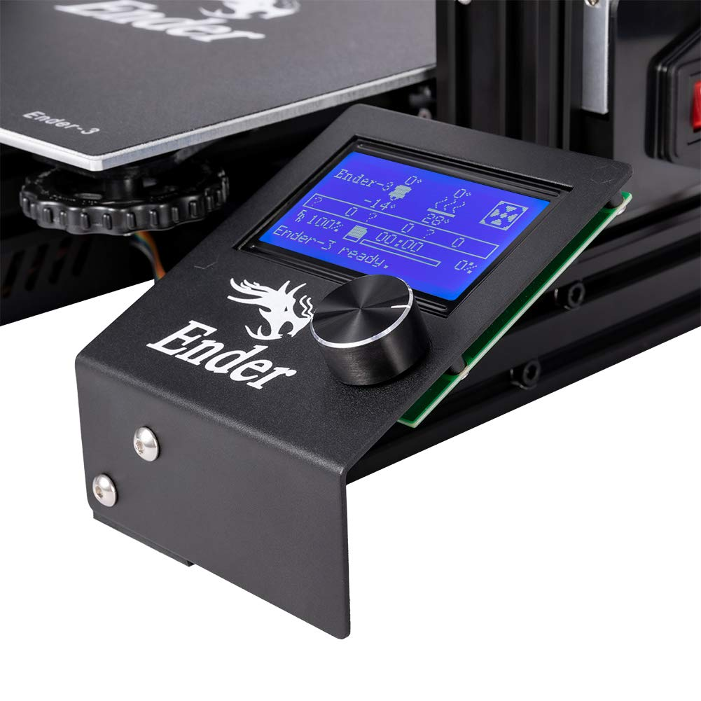
The control button on 3D printers is usually a rotary encoder
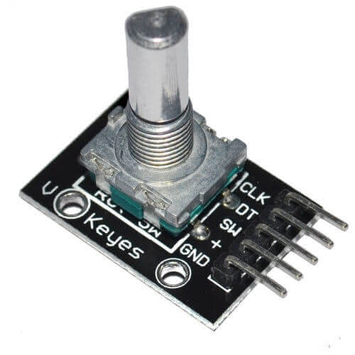
Handling a rotary encoder: the KY-040
This tutorial will explore using a KY-040 rotary encoder module in a DIY project. A rotary encoder is an excellent device for creating a user interface that allows you to choose a menu, increase or decrease a variable, etc. This feature is commonly found in many DIY kits.
Difference between rotary encoder and potentiometer
The rotary encoder KY-040 and the potentiometer may look similar, but they are different. The potentiometer is an analog sensor whose value is determined by its number of turns. On the other hand, the rotary encoder KY-040 is a digital sensor and does not have a limited number of turns like the potentiometer.
The rotary encoder can detect a certain amount of “steps” for each revolution it goes through and sends a signal at each step. It can also turn infinitely, but the difference between it and a potentiometer can be felt through touch. A potentiometer turns smoothly while the rotary encoder turns jerkily.
A rotary encoder can be connected directly to a microcontroller and sends logic levels. Its resolution is based on the number of steps per revolution. In contrast, the resolution of a potentiometer is determined by the resolution of the analog-to-digital converter (ADC) needed to measure its position.
Note
A potentiometer is a device used to adjust values in an analog system, like the volume on an amplifier. A rotary encoder accurately measures the angle and direction of rotation.
How works a rotary encoder work?
This guide does not dive into technical aspects; however, it covers a lot of ground. If you would like to learn more about the physical operation, the various technologies, and the conventional topologies (such as understanding how an optical quadrature phase rotary encoder works 😨), please refer to the theoretical presentation of a rotary encoder.
Wiring the KY-040 rotary encoder to the ESP32
This rotary encoder has 2 signals - CLK and DT - to determine position. Additionally, the SW pin is connected to the integrated push-button switch.
Warning
If you’re new to using rotary encoders, you’ll need to add pull-up resistors to the 3 logic pins. This is the same as when using a primary push-button circuit and is necessary for distinguishing between logic levels.
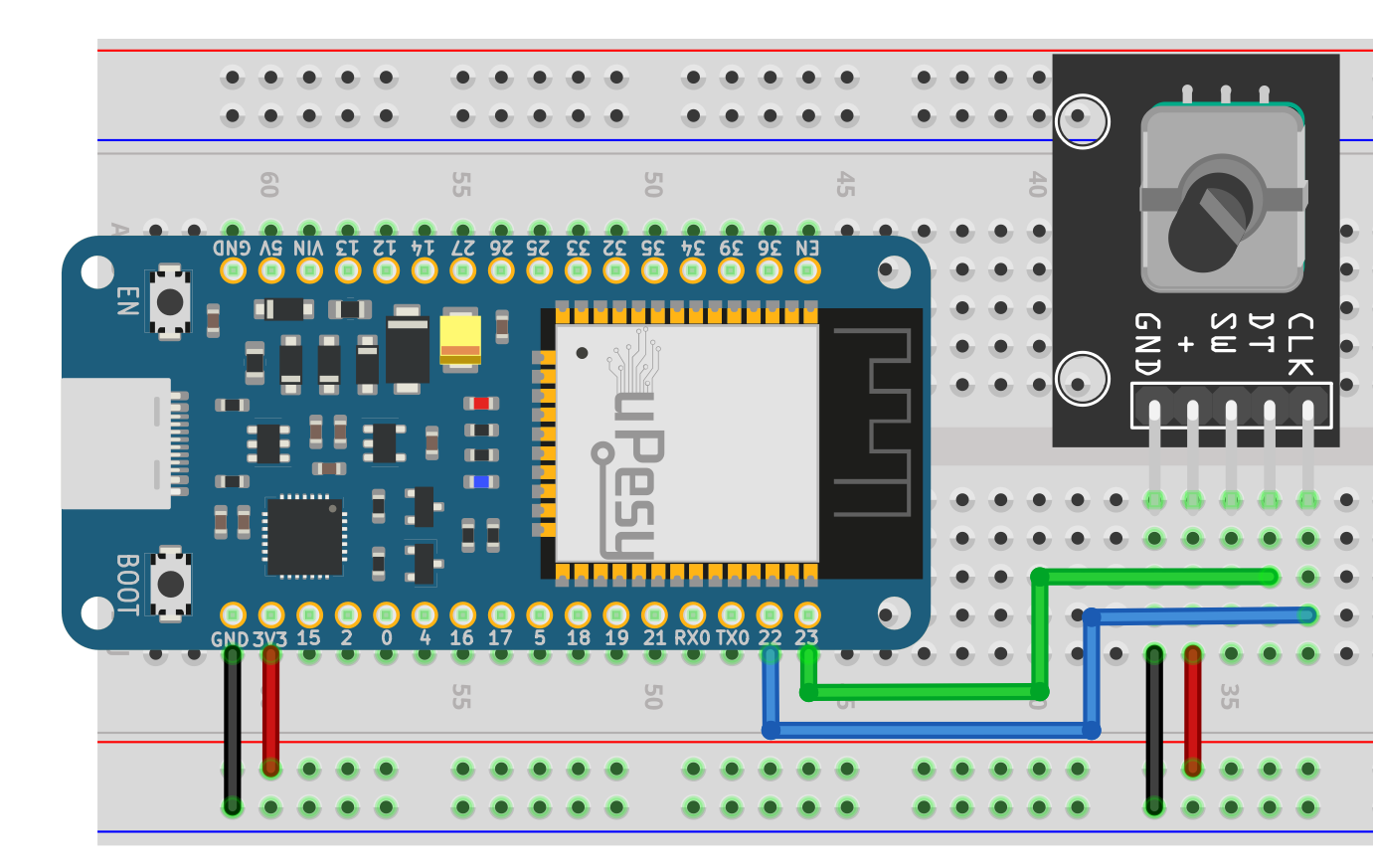
Here is a suggestion to connect to the uPesy ESP32 Wroom DevKit board:
Rotary Encoder |
ESP32 |
|---|---|
|
|
|
|
|
Not used here |
|
|
|
|
The scheme to be done is as follows:
Note
It would help if you supplied the encoder with 3.3V to have 3.3V logic levels (ESP32 friendly).
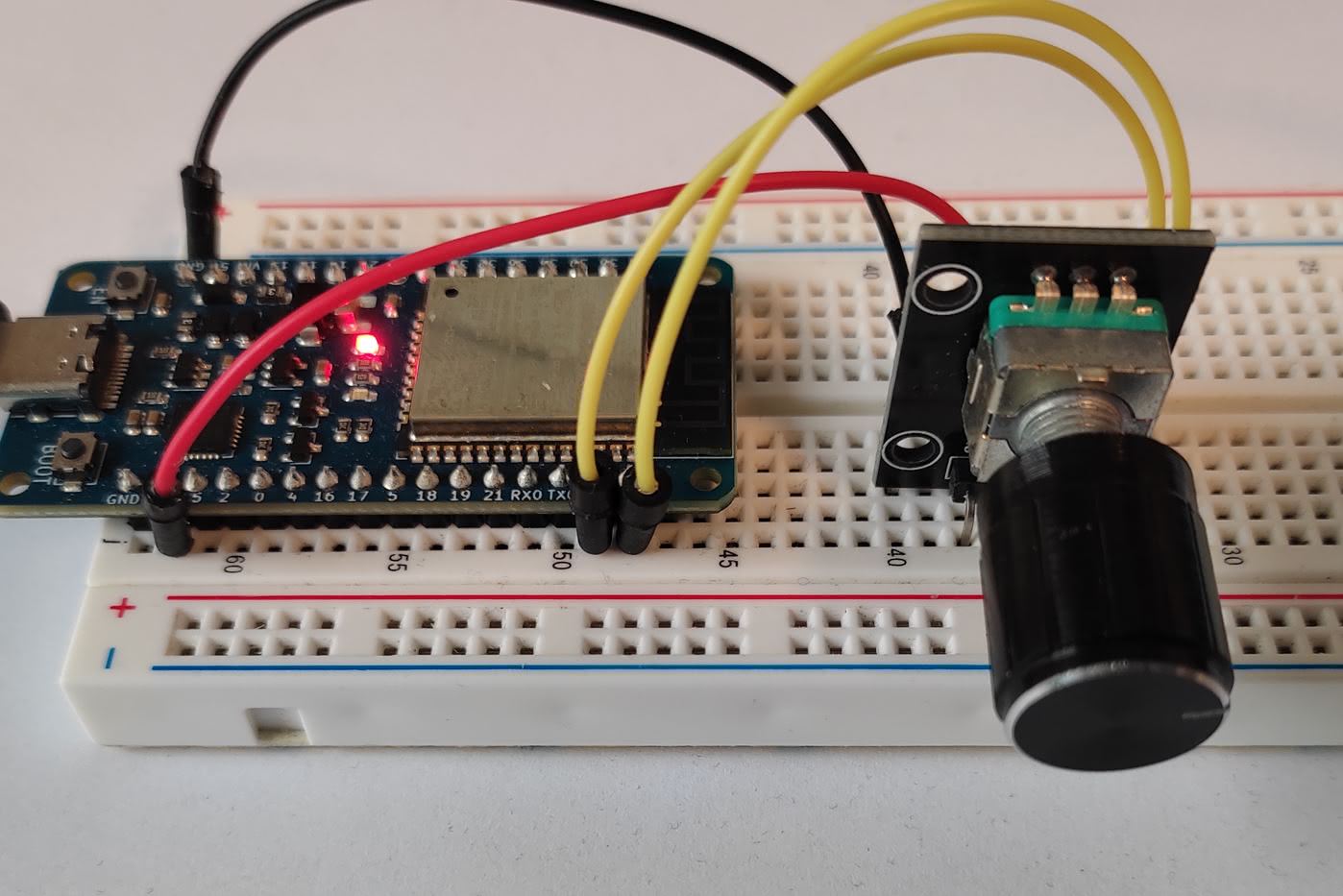
And here is an example of breadboard mounting:
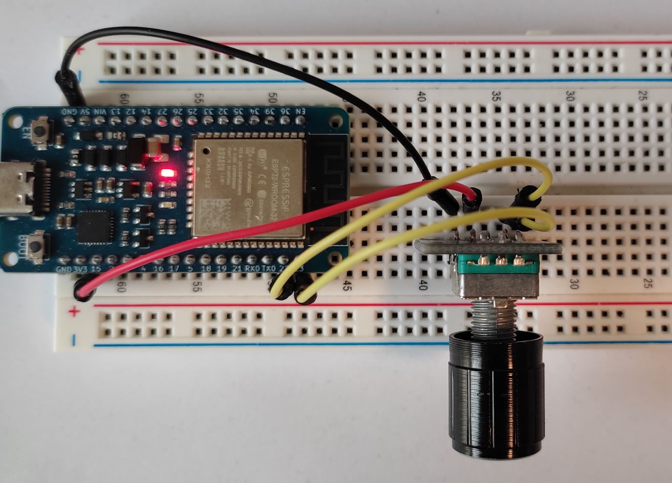
Get the angular position of the KY-040 rotary encoder
Incremental encoders are helpful because they provide information on how many increments are made rather than the angle in degrees. To determine the angle, this information needs to be interpreted by a program. This allows us to determine the increment’s value without knowing the exact angle.
Finding an efficient way to count the steps of an encoder is a critical task. A straightforward approach would be to continuously check if logical signals are being received from the encoder, but this method has its limitations; if the encoder is rotated rapidly, there is a risk that some steps may be missed. Thus, it is ideal to have a reliable method that accurately counts all the steps without blocking the program.
Note
At times, a program may end up counting in the wrong direction. (A classic bug)
An efficient solution is to incorporate hardware interrupts that respond to logic-level changes. This method allows the CPU to remain uninvolved, meaning the code is not blocked.
Note
The ESP32 can attach an interrupt to any output pin.
I recommend utilizing the microPython library micropython-rotary for asynchronously reading the increments of a rotary encoder. This library consists of two files that must be moved to your board, like any other microPython library. This process can be quickly completed within the Thonny IDE.
`rotary.py <https://github.com/miketeachman/micropython-rotary/blob/master/rotary.py>`__`rotary_irq_esp.py <https://github.com/miketeachman/micropython-rotary/blob/master/rotary_irq_esp.py>`__
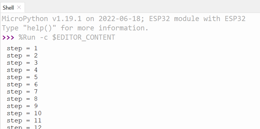
Here is a basic script that allows you to test the library and validate the electrical setup:
import time
from rotary_irq_esp import RotaryIRQ

r = RotaryIRQ(
    pin_num_clk=22,
    pin_num_dt=23,
    reverse=True,
    incr=1,
    range_mode=RotaryIRQ.RANGE_UNBOUNDED,
    pull_up=True,
    half_step=False,
)

val_old = r.value()
while True:
    val_new = r.value()

    if val_old != val_new:
        val_old = val_new
        print("step =", val_new)

    time.sleep_ms(50)
Creating an object of type RotaryIRQ lets you set a variety of options. Please visit the library presentation page for complete details. RotaryIRQ will take care of the work in the background, and the value can be accessed using the r.value() function.
Note
To make it turn the other way, you have two options: reverse the wires CLK and DT of the object, or change the value of reverse when creating it in the script.
In this example, the encoder has no upper limit on the amount it can increment. The variable will increment without bounds until it is full. However, you can set a limit for the increment, for example, -20 to +20 , by altering the range_mode parameter.
Detecting the pressure of the push button
The library does not include a feature to detect a push button. Fortunately, it can be done with MicroPython code similar to how a classic button is detected. An interrupt can also be used to detect the pressing of a button asynchronously. For instance, it can be set up so that pressing the button will reset the count of the current counter.