
Control electrical devices with a Relay, a Pi Pico and MicroPython
(Updated at 01/20/2023)
The relay is an integral part of controlling various devices for home automation projects. The new Raspberry Pi Pico W includes a Wi-Fi module for increased connectivity.
Warning
Working with high voltage is incredibly hazardous and should be done with extreme caution. Invest in professional quality relay modules for long-term use and have your setup reviewed by a specialist before use.
Getting started with a Relay
A relay is very simple, mainly when sold as a module containing a basic circuit.
Note
I strongly advise you to choose a complete module that includes a relay and its minimal circuit rather than using the relay alone and creating the circuit for the logic part yourself (the relay itself cannot be placed on a breadboard and should not be for obvious safety reasons).
Presentation and functioning of a Relay
If you are new to relays and want to understand their use cases and limits better, check out this article which offers a more theoretical overview .
A relay is a mechanical switch that can be controlled with the Raspberry Pi Pico to turn on and off an electrical circuit. This can be a circuit with DC power (such as RGB LED strips or pumps) or a device connected to the 220V mains.
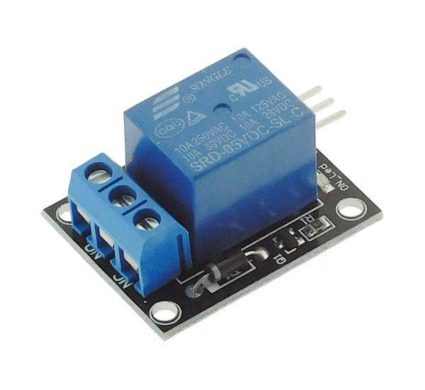
Connection of the SRD-05VDC-SL-C Relay
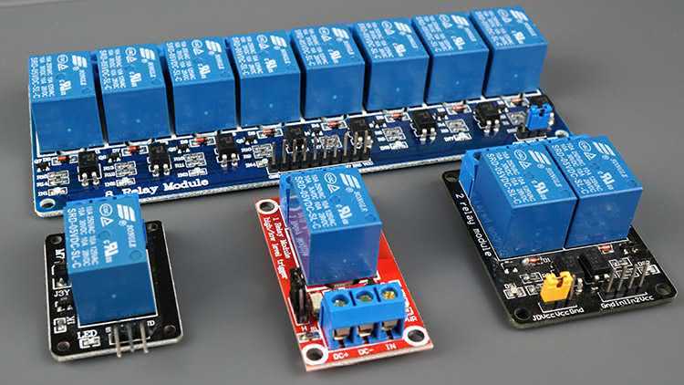
Most of the Arduino kits use the SRD-05VDC-SL-C relay from Songle. These modules are divided into two categories: a module with a single relay and a multi-relay. If you need to drive several power circuits separately, choosing a module with multiple channels is interesting.
Note
This relay should be supplied with 5V (3.3V for the model SRD-03VDC- SL-C).
Warning
Contrary to a schematic with a transistor, it is essential to note that the circuits for power and logic must remain completely separate. Do not connect them, especially if the power circuit involves 220V AC or has no ground!
Relay Module |
Raspberry Pi Pico |
|---|---|
|
|
|
|
|
|
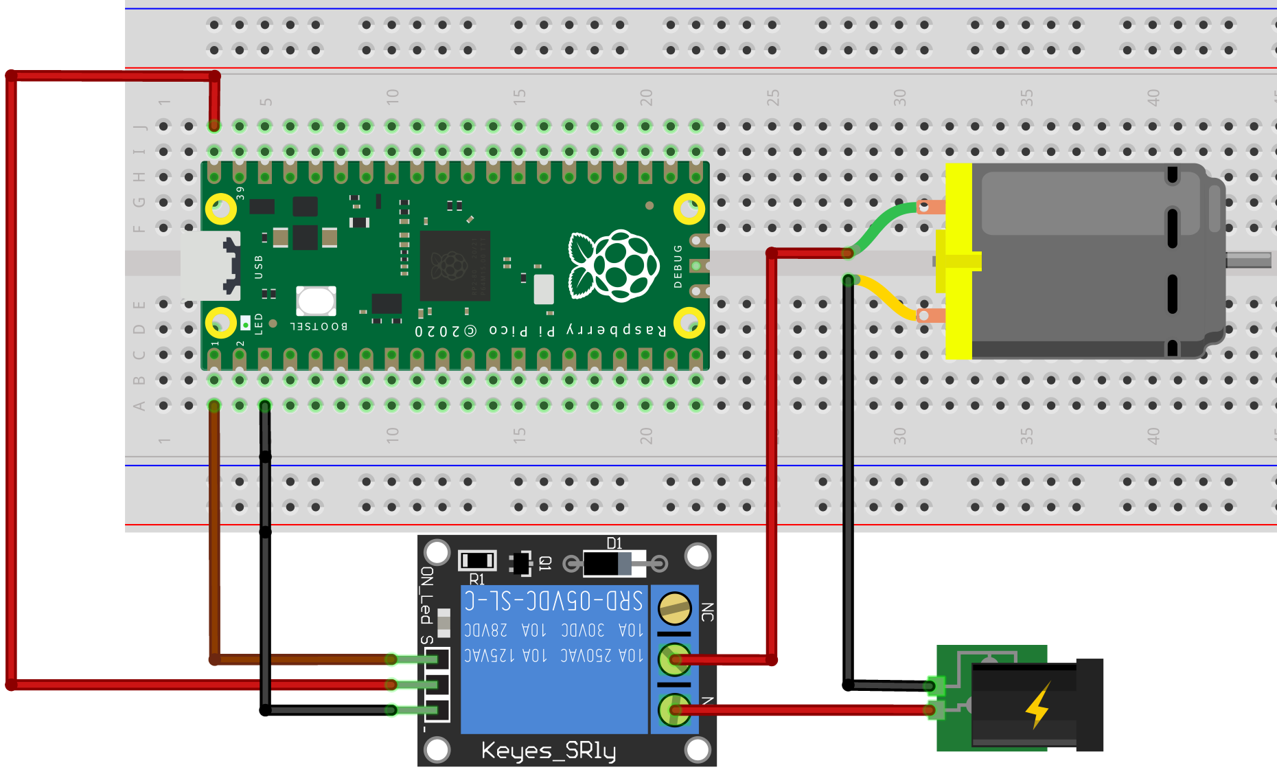
The SRD-05VDC-SL-C model has three pins to control the relay:
The pin
Son the left must be connected to a GPIO pin of the Pi Pico (hereGP0) to send a signal to control the relay.The middle pin represents the power supply that must be connected to the
5V(or to the3V3for model SRD-03VDC-SL-C) of the Pi Pico.The last pin, displayed by
-, is the ground that must be connected to a pinGND.
The module has a 3-pin terminal block, and the relay contacts on the power side :
NC→ Normally Closed contact.COM→ Common contact.NO→ Normally Open contact.
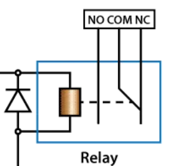
Depending on your application, the device must be connected to the terminals COM and either NO or NC of the relay. When NO is chosen, the circuit is open by default and will only conduct when a signal is sent to the relay.
Choosing COM and NC terminals in an electric circuit will make it closed by default (with the relay inactive): the connected device is turned on. The circuit is opened when the relay is activated and the device is no longer powered.
To prevent accidents, it’s best to choose the safest option if something fails. For instance, if you’re using a device to power a heating resistor, you should use a circuit that opens if the relay malfunctions (when the relay is out of service), as this could help prevent a fire from occurring.
Note
That’s why I recommend you to use COM and NO if the purpose is to switch on a device (lamp, motor, pump).
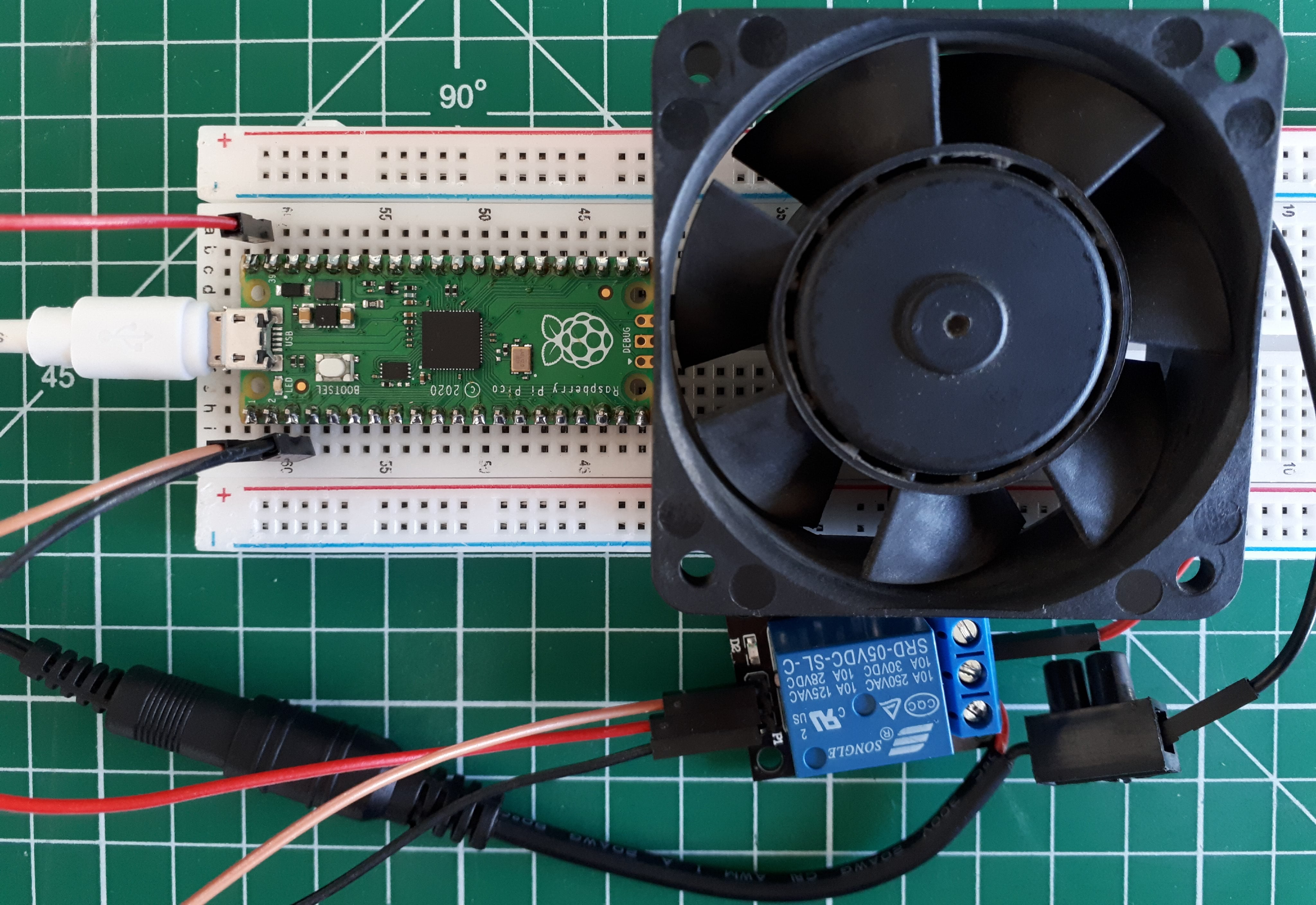
Here is an example of how a relay can be used to switch on a computer fan:
Control the Relay with MicroPython on the Pi Pico
The MicroPython script is relatively straightforward, similar to flipping an LED switch. The code is identical to the classic program blink .
from machine import Pin
import time

pin_relay = Pin(0, mode=Pin.OUT)

while True:
    pin_relay.on()
    time.sleep_ms(200)
    pin_relay.off()
    time.sleep_ms(5000)
And here is what it looks like to turn on the 12V fan:

Note
If you’re looking for a way to regulate the speed of a fan, a transistor circuit may be the ideal solution.
Des modules relais avancés multicanaux
For DIY home automation projects, a range of relay modules is available with 1-8 channels. Each module can control its relays, and the SRD-05VDC-SL-C relay is usually used. Instead of buying multiple single-channel modules, it may be more cost-effective to purchase one large multi-channel module.
Separate the Pi Pico from the Relay with Optocouplers
It is common for modules to have a built-in optocoupler, which is used for complete isolation between the relay and your Pi Pico.
This section is available to premium members only. You still have 77% to discover.
Subscribe for only 5$/monthAlready subscribed? Sign in