
Using a rotary encoder in MicroPython with a Raspberry Pi Pico
(Updated at 01/20/2023)
A rotary encoder is a device that measures the angular position (rotation) of a shaft. It converts it into a signal that can be used to find the position and direction of rotation. They are primarily used in motors to provide better control and in user interfaces to replace potentiometers. Some DIY kits include a rotary encoder with a built-in push-button!
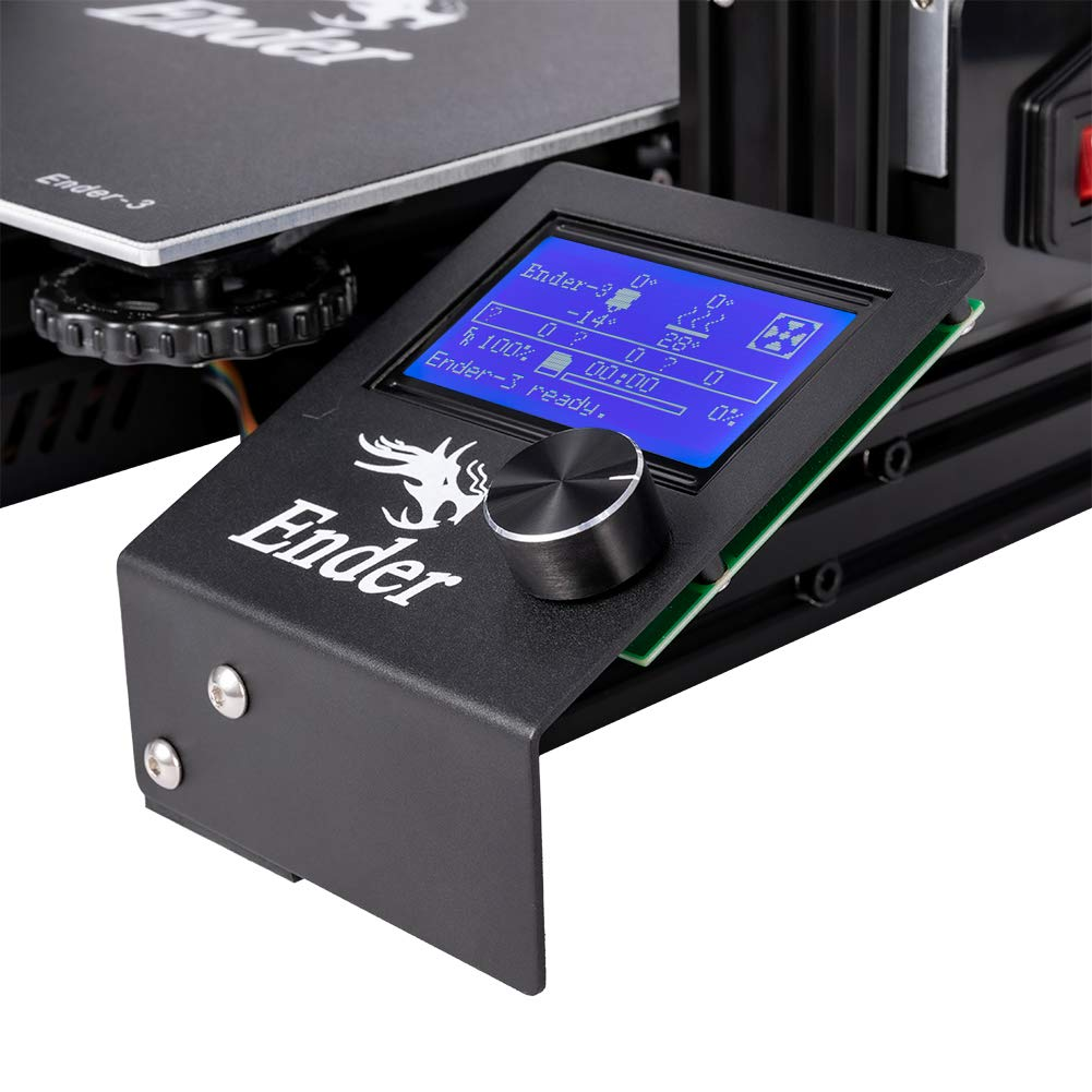
The control button on 3D printers is usually a rotary encoder
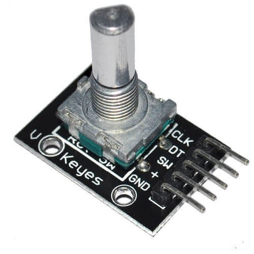
Handling a rotary encoder: the KY-040
This guide will explain using a KY-040 rotary encoder module, a component commonly found in DIY kits. It can be employed in creating user interfaces for programs, such as providing a way to select menus and adjust variables.
Difference between rotary encoder and potentiometer
To the untrained eye, the rotary encoder KY-040 might be mistaken for a potentiometer. In reality, however, a potentiometer is an analog sensor, and a rotary encoder is digital. While a potentiometer changes the value of a resistor, it has a set number of turns that it can make.
A rotary encoder is a device that can detect how many times it rotates and sends a signal each time it turns. It can rotate an infinite number of times. When feeling the difference between a rotary encoder and a potentiometer by touch, the rotary encoder will feel like it is turning in jerky movements, while the potentiometer will turn smoothly.
A rotary encoder is a device with a rotating shaft that sends logic levels that can be read directly by a microcontroller. The resolution of the rotary encoder is based on the number of steps it makes in one revolution. In contrast, the resolution of a potentiometer is based on the precision of the associated Analog-to-Digital Converter (ADC) used to read its position.
Note
A potentiometer is an analog component utilized to adjust settings like the volume of an amplifier. In contrast, a rotary encoder accurately measures the angle and orientation of an object.
How works a rotary encoder?
This tutorial does not cover highly technical information. Suppose you would like to understand the physical operation, technologies and topologies of rotary encoders in greater detail, such as the operation of an optical quadrature phase rotary encoder. In that case, I recommend looking at a:ref:` rotary encoder’s theoretical presentation. <dec1d3cbbdc843cdb291cb08036d3452>`
Wiring of the KY-040 rotary encoder to the Pi Pico
This rotary encoder has 2 signals to know the position: CLK and DT . The pin SW is connected to the integrated push button (SWitch).
Warning
If you’re starting with rotary encoders, you’ll need to add pull-up resistors to the three logic pins. This is similar to using a primary push-button circuit, where resistors are used to tell the difference between logic levels
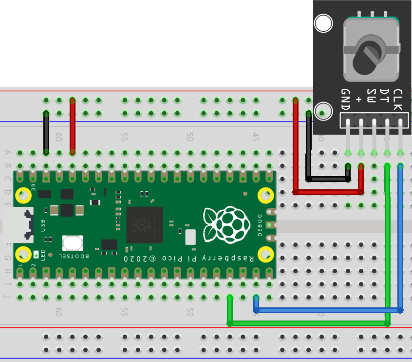
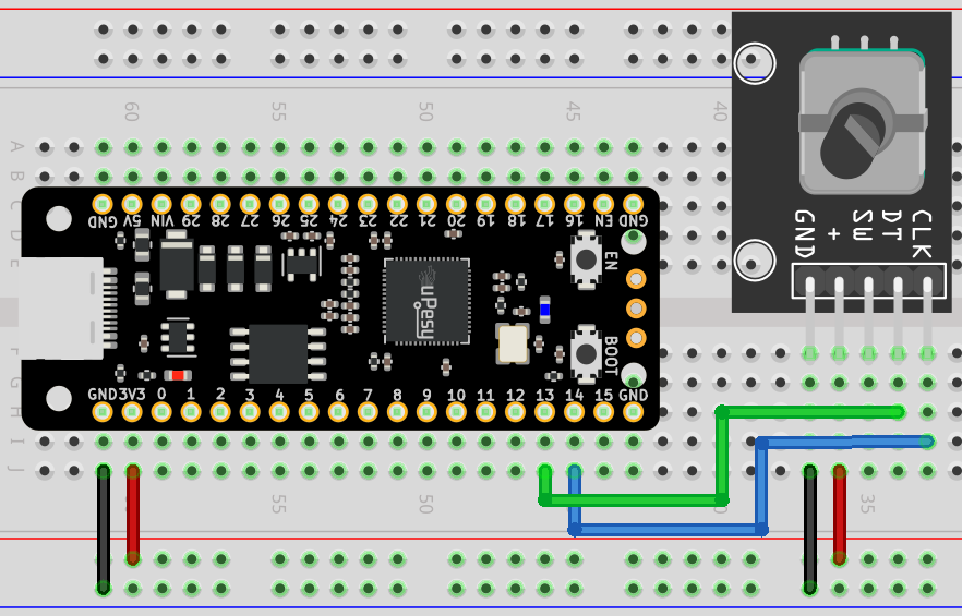
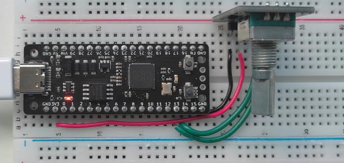
Here is a proposal to connect the Raspberry Pi Pico and the uPesy RP2040 DevKit board:
Rotary Encoder |
Raspberry Pi Pico |
|---|---|
|
|
|
|
|
Pas utilisé ici |
|
|
|
|
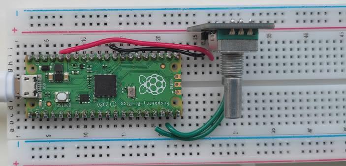
The scheme to be done is as follows:
Note
For best results, it is recommended to provide the encoder with 3.3V power; this will result in 3.3V logic levels, making it compatible with the Raspberry Pi Pico.
And here is an example of breadboard mounting:
Get the angular position of the KY-040 rotary encoder
An incremental encoder does not indicate the angle in degrees but the number of incremental movements made. The angle is calculated in the program, while we only need to know the value of the increment.
Finding the number of encoder “steps” can be done in a few different ways. The best approach is to use a secure method to keep up with the program without getting blocked. If a more uncomplicated tactic is used, such as constantly scanning for encoder signals, any rapid encoder turns may cause some steps to be missed.
Note
If the program cannot process data quickly enough, it may display an incorrect count. (A classic bug)
The best way to detect a change in the logical level is to use hardware interrupts. This type of interrupt will not require CPU processing, meaning the code will be non-blocking.
Note
The Raspberry Pi Pico allows interrupts to be set up on any pin, unlike Arduinos, which only provide a few pins for interrupts.
For those new to micropython, the microPython library micropython-rotary is a great way to read increments of a rotary encoder asynchronously. It consists of two files that must be transferred to your board. This can be done quickly and easily using Thonny IDE:
`rotary.py <https://github.com/miketeachman/micropython-rotary/blob/master/rotary.py>`__:`rotary_irq_rp2.py <https://github.com/miketeachman/micropython-rotary/blob/master/rotary_irq_rp2.py>`__:
Here is a fundamental script that allows you to test the library and validate the electrical setup:
import time
from rotary_irq_rp2 import RotaryIRQ

r = RotaryIRQ(
    pin_num_clk=14,
    pin_num_dt=13,
    reverse=False,
    incr=1,
    range_mode=RotaryIRQ.RANGE_UNBOUNDED,
    pull_up=True,
    half_step=False,
)

val_old = r.value()
while True:
    val_new = r.value()

    if val_old != val_new:
        val_old = val_new
        print("step =", val_new)

    time.sleep_ms(50)
When creating a RotaryIRQ object, there are a variety of settings you can adjust. These are outlined in detail on the library presentation page. The changes you make will be handled in the background, and you can retrieve their value via the r.value() function at any time.
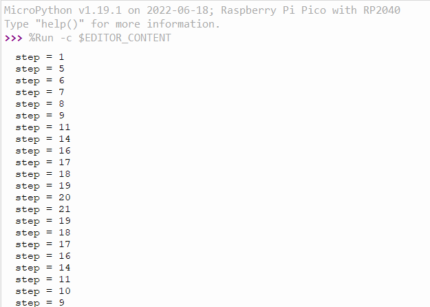
In this example, the encoder count can go up without end (till the variable overflows). You may set a specific range for the increment, e.g., -20 to +20 , by modifying the range_mode parameter.
Detecting the pressure of the push button
The library does not provide a push-button detection feature. Nevertheless, it can be accomplished in MicroPython code by detecting a classic button. An interrupt may also indicate when the button is pressed, such as resetting a counter.
Use the PIO pins of the Pi Pico
This section is available to premium members only. You still have -1190% to discover.
Subscribe for only 5$/monthAlready subscribed? Sign in