Control ESP32 GPIO Pin
(Updated at 11/28/2022)
The functions to be used are the same as with an Arduino. We use the pinMode() method to configure a pin as a digital input or output, the digitalWrite() function to impose a voltage of 0V or 3.3V on the output and the digitalRead() function to read a logic level (either 0V or 3.3V) on the input.
Note
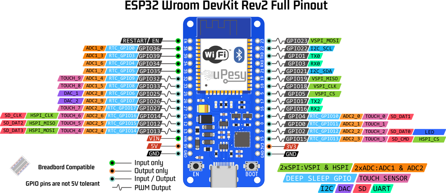
The pin numbers are those indicated in the grey “GPIO” insert on the board’s pinout. Even if there is a link between the number of GPIO pins of the ESP32 and those usually used on the Arduino, to avoid confusion, it is better not to use them and to use the native pins number of ESP32 exclusively. You should therefore avoid using A0, MOSI, SCK, SDA …
Configuration of ESP32 input or output pins
Configuration of the GPIO2 pin as output:
pinMode(2, OUTPUT);
Configuration of the GPIO15 pin as input:
pinMode(15, INPUT);
A quick reminder on pull-up and pull-down resistors
The measured value is random if we measure a voltage from a pin that is not connected to the ground or a non-zero voltage. This is due to the electrical noise generated by several factors (the wire behaves in particular like an antenna). The most concrete example is when you use a push button.
Two ways to eliminate noise and get reliable measurements :
With a pull-up resistor
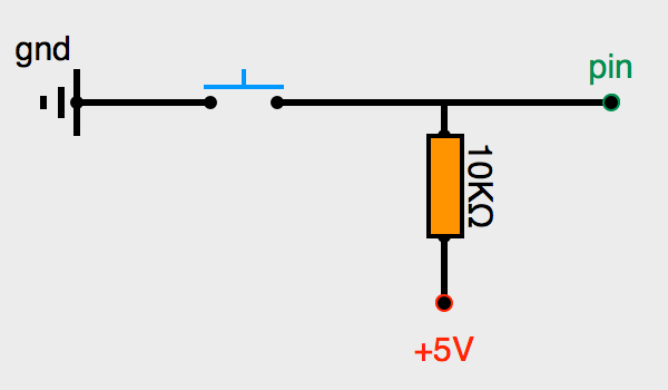
This circuit allows only two possible voltages: 0V when the button is pressed; otherwise +3.3V
When the switch is opened (button released), the + 3.3V feeds the pin of the ESP32, and the measured value of the pin will give HIGH (or 1).
When the switch is closed (button pressed), the +3.3V and the pin are absorbed by the mass. The pin measurement will give LOW (or 0).
With a pull-down resistor
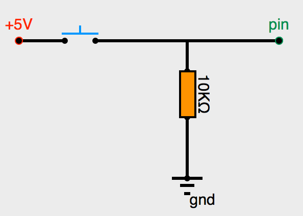
This circuit allows you to have only two possible voltages: +3.3V when you push the button; otherwise, 0V.
If the push button is pressed, the current goes from +3.3V to the pin of the ESP32. It will not take the path of the mass because the current always flows by the least resistive path. The ESP32 pin will receive +3.3V and indicate HIGH (or 1).
If the push button is released, the circuit is opened. The mass will absorb the very low residual current. The pin will therefore be in LOW (or 0).
All GPIO pins (except GPIO36, GPIO39, GPIO34, and GPIO35 pins) have these two circuits internally in the ESP32.
Use ESP32 internal pull-up and pull-down resistors
Configuration of the GPIO15 pin as input with the internal pull-up resistor:
pinMode(15, INPUT_PULLUP);
Configuration of the GPIO15 pin as input with the internal pull-down resistor :
pinMode(15, INPUT_PULLDOWN);
Note
Unlike the Arduino, on the ESP32, there are internal pull-down resistors.
Set or read a voltage
To set a voltage of 3.3V at the output of pin 2 of the ESP32:
pinMode(2, OUTPUT); // set the pin as output
digitalWrite(2, HIGH)
Note
The output voltage of pins is 3.3V (and not 5V like on Arduino)
To read a voltage of a logic level of 0V or 3.3V on pin 15 of the ESP32:
pinMode(15, INPUT); // set the pin as input
digitalRead(15);
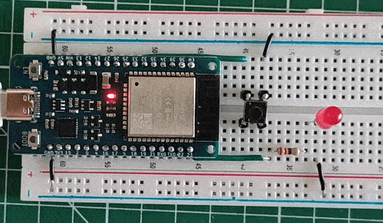
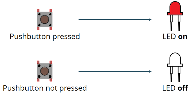
Mini-Project: Controlling an LED with a button
To show how to use the digital inputs/outputs of the ESP32, we will accomplish a short project that turns on the LED when a button is pressed.
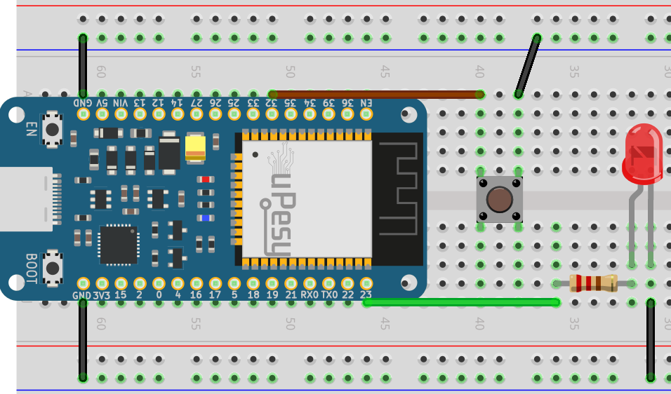
Electrical schematic
We will use the internal pull-up resistors to simplify the electronic schematic.
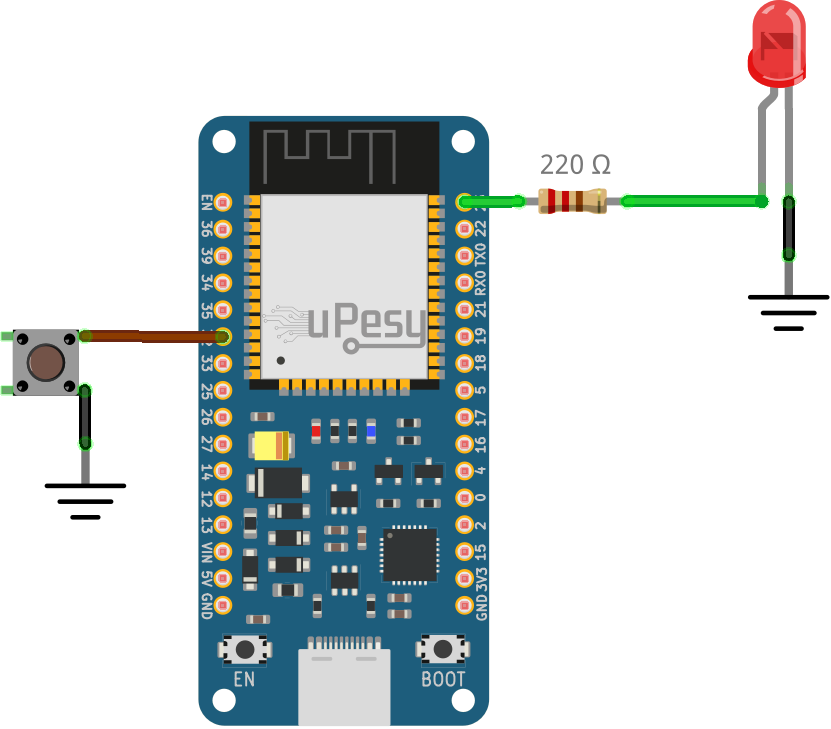
Warning
Do not forget to plug the push button deeply into the breadboard.
Code to turn on the LED when the button is pushed
Solution
const int buttonPin = 32;
const int ledPin =  23;

// State of the push button
int buttonState = 0;

void setup() {
    Serial.begin(115200);

    //Set the pin as an input pullup
    pinMode(buttonPin, INPUT_PULLUP);
    pinMode(ledPin, OUTPUT);
}

void loop() {

    buttonState = digitalRead(buttonPin);
    Serial.println(buttonState);

    if (buttonState == LOW) {
        // Switch on the led
        digitalWrite(ledPin, HIGH);
    } else {
        // Switch off the led
        digitalWrite(ledPin, LOW);
    }
}
Final result