
Measure an analog voltage with the Pi Pico ADC in MicroPython
(Updated at 12/26/2022)
Some pins are connected to the internal ADC on the Raspberry Pi Pico. An Analog-Digital Converter returns a digital value proportional to the measured input voltage.
Features
Pins 26 , 27 and``28`` can be used as analog input on the Raspberry Pi Pico. The resolution of the measured values is 16 bits, so the values are between 0 and 65535.
Note
On the board uPesy RP2040 DevKit, there is an additional analog input on pin 29 .
Tip
A “hidden” analog input in the RP2040 microcontroller allows direct measurement of the chip temperature. This is somewhat equivalent to the temperature measurements of computer CPUs. We should not use it to get the room temperature. This input corresponds to ADC_4 .
Warning
Unlike the Arduino, the analog inputs of the Pico must not exceed a voltage of 3.3V. This could damage or destroy the ADC inputs. It is, therefore, essential not to use a supply voltage of 5V to measure the value of a sensor. There are solutions to limit the input voltage of the ADC.
Read an analog input from the Pico with MicroPython.
The voltage of analog input is measured using the sub-module ADC of the machine . As for PWM, a physical pin is associated with the object ADC .
from machine import Pin, ADC

# Pin definitions
adc_pin = Pin(26, mode=Pin.IN)
adc = ADC(adc_pin)
Don’t forget to import the ADC sub-module. You can also create an ADC by specifying the number of the analog channel you want to use.
from machine import ADC
adc = ADC(0) # Select the ADC_0
Once you have configured an analog input in MicroPython, you must use the function read_u16() on the Raspberry Pi Pico to read the analog value.
from machine import Pin, ADC
adc = ADC(Pin(26, mode=Pin.IN))
print(adc.read_u16())
It will be necessary to make a cross product to convert the binary value into volts:
Measure the internal temperature of the Raspberry Pi Pico
The Raspberry Pi Pico has an internal temperature sensor to measure the temperature of the RP2040 chip. Although not very reliable to have the room temperature, it allows us to know the temperature of the chip (like the temperature of the CPU on computers). This sensor is directly connected to the ADC_4 of the ADC.
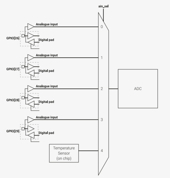
The internal temperature sensor is located on the last pin of the ADC
To measure the temperature, you need:
Retrieve the raw analog value from the temperature sensor available on channel 4 of the ADC
Convert this value to voltage
Use a formula given in the RP240 documentation to convert this voltage to temperature (in °C)
from machine import ADC
import time

temp_sensor = ADC(4)

while True:
    adc_voltage = temp_sensor.read_u16() * 3.3 / 65535
    cpu_temp = 27 - (adc_voltage - 0.706)/0.001721 # Formula given in RP2040 Datasheet
    print(cpu_temp)
    time.sleep_ms(1_000)
Note
You can see the temperature change by putting your finger on the RP2040 chip.
REPL console output:
32.19402
32.19402
32.66216
31.72584
33.13027
33.59842
34.06656
34.06656
34.53474
34.06656
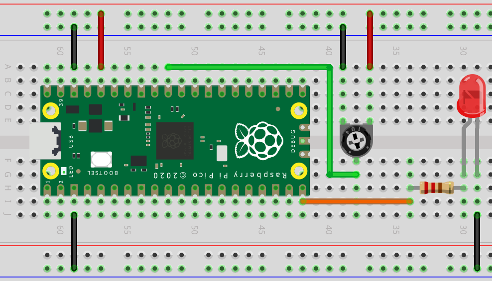
Mini-Project: Control the intensity of an LED with a potentiometer
We will use PWM, ADC and MicroPython to control the intensity of an external LED.

Note
Remember to put a resistor in series with the LED to prevent it from burning (330 Ω, for example)
To read the position of the potentiometer only :
from machine import Pin, ADC
import time


# Create an ADC object linked to pin 26
adc = ADC(Pin(26, mode=Pin.IN))

while True:

    # Read ADC and convert to voltage
    val = adc.read_u16()
    val = val * (3.3 / 65535)
    print(round(val, 2), "V") # Keep only 2 digits

    # Wait a bit before taking another reading
    time.sleep_ms(100)
For the reading of the potentiometer position and the variation of the brightness :
from machine import Pin, ADC, PWM
import time

# Create a PWM object linked to pin 15
pwm_led = PWM(Pin(15,mode=Pin.OUT))
pwm_led.freq(1_000)

# Create an ADC object linked to pin 26
adc = ADC(Pin(26, mode=Pin.IN))

while True:

    val = adc.read_u16()
    pwm_led.duty_u16(val)
    time.sleep_ms(10)