
ESP32 Wroom Devkit Pinout: Use the ESP32 GPIO pins
(Updated at 03/21/2023)
Find all the relevant information about the ESP32 pinout on a single page to use these GPIO pins for your DIY electronics project correctly. Even though there are many variations of ESP32 boards, the function of the pins remains the same. However, some pins may not be available, depending on your model.
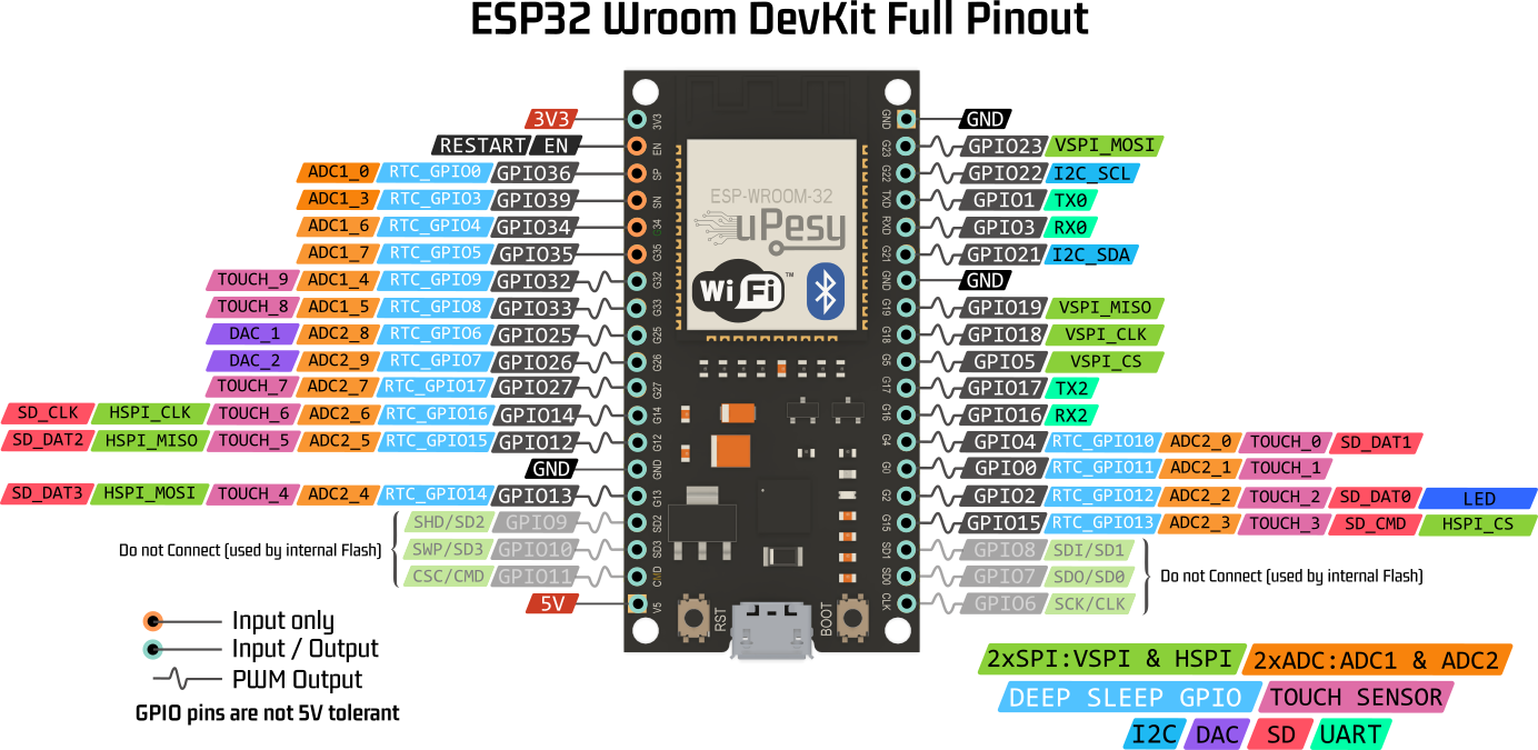
There are plenty of ESP32 boards out there with different pin arrangements. Here is a detailed pin diagram of 2 different ESP32 boards. It will be beneficial to know the specific functions of each pin:
ESP32 WROOM Generic DevKit
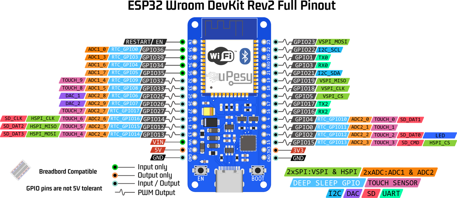
uPesy ESP32 WROOM DevKit
Note
A significant difference between the two boards that are not necessarily obvious is their width: The uPesy ESP32 board can be put on a breadboard, and you can access the pins on both sides, unlike most other ESP32 boards that are too “big” to be used on a breadboard …
The particular behavior of some pins of the ESP32
The goal is to inform you about the limitations of some GPIO pins of the ESP32 to avoid unpleasant surprises during your projects or having an incomprehensible bug in your code.
ESP32-based development boards typically have 33 pins except those for the power supply. Some GPIO pins have a little bit particular functionings:
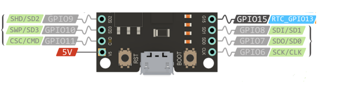
If your ESP32 board has the GPIO6, GPIO7, GPIO8, GPIO9, GPIO10, and GPIO11 pins, you must not use them because they are connected to the flash memory of the ESP32: if you use them, the ESP32 will not work.
GPIO |
Possible name |
|---|---|
6 |
SCK/CLK |
7 |
SDO/SD0 |
8 |
SDI/SD1 |
9 |
SHD/SD2 |
10 |
SWP/SD3 |
11 |
CSC/CMD |
Note
For this reason, these pins are not available on uPesy ESP32 boards.
The GPIO1 (TX0) and GPIO3 (RX0) pins are used to communicate with the computer in UART via USB. If you use them, you will not be able to upload programs to the board or use the serial monitor via the USB port. They can be useful for programming the board without a USB but with an external programmer instead. Fortunately, there are other UART interfaces available.
Pins GPIO36 (VP), GPIO39 (VN), GPIO34, and GPIO35 can only be used as input. They also do not have internal pull-up and pull-down resistors (
pinMode(36, INPUT_PULLUP)orpinMode(36, INPUT_PULLDOWN)cannot be used).Some pins have a unique function when starting the ESP32. These are called ESP32 Strapping Pins .
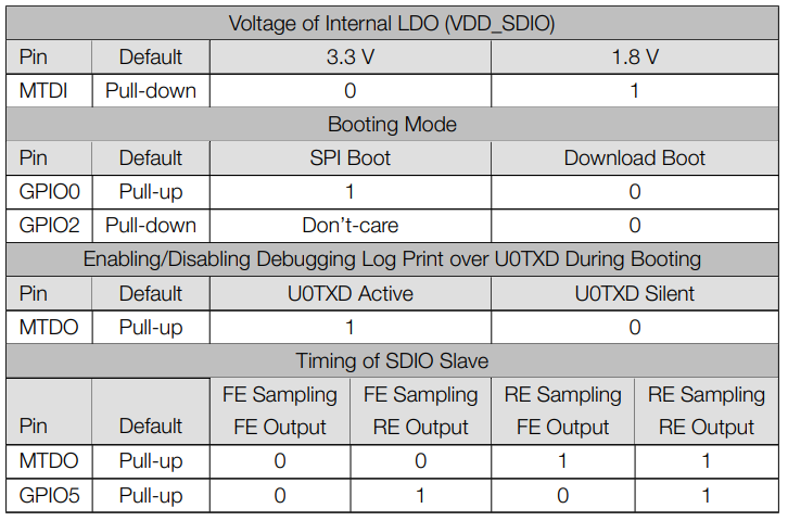
They are used to put the ESP32 in BOOT mode (to run the program written in the flash memory) or in FLASH mode (to upload the program to the flash memory). Depending on the voltage available on these pins, the ESP32 will start either in BOOT mode or in FLASH mode.
The strapping pins are the GPIO0, GPIO2, GPIO12 (MTDI) and GPIO15 (MTDO) . You can use them, but you must be careful when setting a logic state (3.3V or 0V) with an external pull-up or pull-down resistor.
Tip
If your ESP32 board works correctly, but when you add a sensor, nothing works anymore (it is impossible to upload a program or launch it), it is most likely related to these famous strapping pins.
When booting the ESP32, during a short period, some pins quickly change their logic states (0V → 3.3V). You may have weird bugs with these pins: for example, a relay that temporarily activates. The faulty pins are the following:
GPIO 1 : Sends the ESP32 boot logs via the UART
GPIO 3 : 3.3V voltage at boot time
GPIO 5 : Sends a PWM signal at boot time
GPIO 14 : Sends a PWM signal at boot time
GPIO 15 : Sends the ESP32 boot logs via the UART
Note
Note that we can use these pins. If you encounter a strange behavior when starting the ESP32 by using one of these pins, you will probably have to choose another one.
The EN pin can activate or deactivate the ESP32 via an external wire. It is connected to the board’s EN button. When the ESP32 is on, it is at 3.3V. If you put this pin to the ground, the ESP32 is off. This can be used when the ESP32 is in a box and you want to be able to turn it on/off with a switch.
On boards that use an ESP32-WROVER module to have more RAM (for example, on the uPesy ESP32 Wrover DevKit board ), then the GPIO16 and GPIO17 pins are not available because they are used internally by the PSRAM.
Others GPIO pins have no particular restrictions.
Summary of all ESP32 GPIO pins
ESP32 Peripherals
To interact with the modules, sensors or electronic circuits, the ESP32, like any microcontroller, has a multitude of peripherals. They are much more numerous than on a classic Arduino Uno board.
The ESP32 has the following peripherals:
The ESP32 already uses some peripherals in its essential operation. So, in reality, there are fewer possible interfaces for each device.
Tip
The pins of the ESP32 are much more modular than those of the Arduino: You can “ attach “ a UART, I2C, SPI, and PWM peripheral on the pins you want. The SPI, I2C, UART, PWM, and DAC are no longer associated with specific pins. For example, on the Arduino Uno, you could only have SPI on pins 10, 11, 12, and 13. With the ESP32, you can choose the ones you want. Only the ADC and the capacitive sensors are assigned to fixed pins. ESP32 Pinouts available on the Internet show the default association (if you do not specify the pins used). It remains a good practice to use the pins by default to keep good compatibility with external libraries as long as this does not limit the connection of your wires.
UART on ESP32
The UART is the serial protocol that allows easy data exchange between 2 devices. On the ESP32, 3 UART buses are available: UART0, UART1 and UART2. We can use them to communicate with a sensor, an Arduino, a Raspberry Pi, a computer …
The UART0 is by default on pins GPIO1(TX0) and GPIO3(RX0) of the ESP32. It is used to communicate with the computer through the serial monitor. It is also the one used to flash the ESP32 board when uploading a new program. It generally displays messages in the console with
Serial.println().To use the UART2, simply add
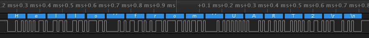
Serial2.begin()in the functionsetup()and to use the``Serial2.println()`` to send messages. By default, the UART2 bus is on pins GPIO16(RX2) and GPIO17(TX2), but you can change them (useful with a Wrover module) during setup. This simple code allows you to use the UART2 bus:void setup() { Serial2.begin(115200); } void loop() { Serial2.println("Hello from UART2"); delay(100); }
Note
The message will not be displayed on the serial monitor since the UART2 is not connected to the computer’s USB.
The UART1 is by default on the pins used by the ESP32 flash. However, We can use it by choosing the pins you want, thanks to the “GPIO matrix” of the ESP32. Thus this code allows having a serial interface on the pins GPIO14 and GPIO12 by using the UART1 bus.
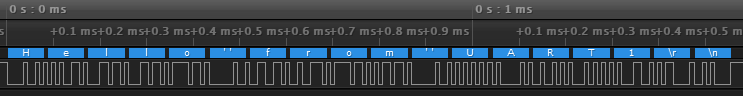
void setup() {
  /*
  * UART1  -> Serial1
  * RX Pin -> GPIO 14
  * TX Pin -> GPIO 12
  * UART Configuration -> SERIAL_8N1
  */
  Serial1.begin(115200,SERIAL_8N1,14,12);

}

void loop() {
  Serial1.println("Hello from UART1");
  delay(100);
}
I2C on ESP32
The ESP32 has 2 I2C buses :
The I2C0 bus is the one used by default by Arduino libraries. It is connected to the pins GPIO22 (SCL) and GPIO21 (SDA) of the ESP32. It can be used on any pin of the ESP32 when you use the
Wire.hlibrary by specifying the pins with the functionWire.begin(SDA_PIN, SCL_PIN).The I2C1 bus can also be used on any pin (pay attention to the “limited pins” described previously). Here is an example that uses the second I2C bus:
#include <Wire.h>

TwoWire I2C1 = TwoWire(1);

void setup() {
  I2C1.begin(14,12,400000); // SDA pin 14, SCL pin 12, 400kHz frequency
}

void loop() {
  I2C1.beginTransmission(0x42);
  I2C1.write(140);
  I2C1.endTransmission();
  delay(100);
}
SPI on ESP32
Even if the ESP32 has 3 SPI buses, we can use only two because the internal flash memory uses one. The two available SPI buses are called VSPI and HSPI.
Note
Arduino libraries that use SPI use the VSPI bus by default.
By default, the pin mapping is as follows:
SPI |
MOSI |
MISO |
SCK/CLK |
CS/SS |
|---|---|---|---|---|
VSPI |
GPIO 23 |
GPIO 19 |
GPIO 18 |
GPIO 5 |
HSPI |
GPIO 13 |
GPIO 12 |
GPIO 14 |
GPIO 15 |
As for the I2C, it is possible to manually choose the pins you want to use for the SPI by specifying the pins during the initialization of the SPI bus.begin(CLK_PIN, MISO_PIN, MOSI_PIN, SS_PIN);
PWM on ESP32
The ESP32 has 16 channels that can be used to generate PWM signals: you can have up to 16 different PWM outputs. All the pins configured as output can be used to output a PWM signal. The use of PWM differs from Arduino’s, and you can configure more parameters. I suggest you check the usage of PWM on ESP32 with Arduino code to use it in your projects.
Capacitive sensors on the ESP32
The ESP32 has ten capacitive sensors (9 if the GPIO0 pin is unavailable). They can be used as touch buttons. They are the famous TOUCH pins that can be found on some ESP32 pinouts. They can also be used to wake it up when the ESP32 is in DeepSleep mode (a power-saving mode). I invite you to read the use of capacitive sensors on the ESP32 with the Arduino code for more details.
The internal capacitive sensors are connected to the following GPIO pins:
TOUCH0 |
TOUCH1 |
TOUCH2 |
TOUCH3 |
TOUCH4 |
|---|---|---|---|---|
GPIO 4 |
GPIO 0 |
GPIO 2 |
GPIO 15 |
GPIO 13 |
TOUCH5 |
TOUCH6 |
TOUCH7 |
TOUCH8 |
TOUCH9 |
GPIO 12 |
GPIO 14 |
GPIO 27 |
GPIO 33 |
GPIO 32 |
ADC on ESP32
The ESP32 has two separate ADC: ADC1 with eight channels and ADC2 with ten channels for a total of 18 analog inputs. For example, on the GPIO34, you will find channel number 6 of the ADC1 (ADC1_CH6). But in practice, there are far fewer available because of Wi-Fi.
Warning
The ADC2 cannot be used when Wi-Fi is enabled: The ESP32 Wi-Fi driver uses it to work.
ADC1_CH0 |
ADC1_CH1 |
ADC1_CH2 |
ADC1_CH3 |
|---|---|---|---|
GPIO 36 |
GPIO 37 |
GPIO 38 |
GPIO 39 |
ADC1_CH4 |
ADC1_CH5 |
ADC1_CH6 |
ADC1_CH7 |
GPIO 32 |
GPIO 33 |
GPIO 34 |
GPIO 35 |
Note
Generally, the GPIO37 and GPIO38 pins are not available if your board has a WROOM or WROVER module. These modules do not expose these pins. Only boards that use the ESP32 board directly (without a module) may expose them.
ADC2_CH0 |
ADC2_CH1 |
ADC2_CH2 |
ADC2_CH3 |
ADC2_CH4 |
|---|---|---|---|---|
GPIO 4 |
GPIO 0 |
GPIO 2 |
GPIO 15 |
GPIO 13 |
ADC2_CH5 |
ADC2_CH6 |
ADC2_CH7 |
ADC2_CH8 |
ADC2_CH9 |
GPIO 12 |
GPIO 14 |
GPIO 27 |
GPIO 25 |
GPIO 26 |
In general, the ESP32 ADC is not very reliable despite its 12-bit resolution. I invite you to read the article on the use and limitations of the ESP32 ADC for more information.
DAC on ESP32
The ESP32 has two 8-bit DAC outputs to convert a digital signal into an analog signal (generate a sine signal, for example). The pins used are the following:
DAC1 |
DAC2 |
|---|---|
GPIO 25 |
GPIO 26 |
Note
The DAC only has a resolution of eight bits. It is insufficient for audio applications without deterioration. It is better to use an external DAC with a higher resolution (12-24 bits) with the I2S bus of the ESP32.