
Create ESP32 GPIO Interrupts to reduce CPU usage
(Updated at 11/28/2022)
An interrupt is a function triggered asynchronously by an external event that momentarily interrupts the current code’s execution to execute more critical code.
What’s the point?
Imagine that you want to turn on an LED when you press a button connected to a GPIO pin of the ESP32. The simplest way is to look permanently in the function loop() if you have pressed the :
const int buttonPin = 33;
const int ledPin =  2;

// Push button status
int buttonState = 0;

void setup() {
    Serial.begin(115200);

    //Configuration of the input pin in pullup
    pinMode(buttonPin, INPUT_PULLUP);
    pinMode(ledPin, OUTPUT);
}

void loop() {
    buttonState = digitalRead(buttonPin);

    if (buttonState == LOW) {
        digitalWrite(ledPin, HIGH);
    } else if(buttonState == HIGH){
        digitalWrite(ledPin, LOW);
    }
}
The problem is that this task keeps the microcontroller’s processor busy. So we can tell the microcontroller to do other tasks in the loop() , but in this case, the microcontroller will only look at the state of the button once at each iteration of the loop() . We may miss an event. We can’t process real-time external events. Interrupts allow detecting an event in real-time while letting the microcontroller processor do other tasks. Thus the operation of an interrupt is as follows :
Detection of an event → Interruption of the main program → Execution of the interrupt code → The processor picks up where it left off.
Note
With interrupts, there is no need to look at pin value constantly: when a change is detected, a function is automatically executed.
Detection modes
The detection of an event is based on the signal shape that reaches the pin.
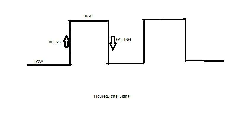
You can choose the interruption detection mode:
LOWtriggers the interrupt as soon as the signal is at 0VHIGHtriggers the interrupt as soon as the signal is 3.3VRISINGtriggers the interrupt as soon as the signal changes fromLOWtoHIGH(0 to 3.3V)FALLINGtriggers the interrupt as soon as the signal changes fromHIGHtoLOW(3.3V to 0)CHANGEtriggers the interrupt as soon as the signal changes fromLOWtoHIGHor fromHIGHtoLOW.
Note
RISING and FALLING mods are the most commonly used. Note that if you use the LOW and HIGH the interrupt will be triggered in a loop as long as the signal does not change state.
Use on the ESP32
The use of interrupts on the ESP32 is similar to that on the Arduino with the attachInterrupt() . We can use any GPIO pin for interrupts.
Thus to create an interrupt on a pin, you must :
Assign a pin to detect the interrupt
attachInterrupt()attachInterrupt(GPIOPin, function_ISR, Mode);
With
Mode, the detection mode can beLOW,HIGH,RISING,FALLINGorCHANGECreate the function that will be executed when the interrupt is triggered
void IRAM_ATTR function_ISR() {
  // Content of the function
}
Note
It is recommended to add the flag
IRAM_ATTRso that the function code is stored in RAM (and not in Flash) so that the function runs faster.The entire code will be of the form :
void IRAM_ATTR function_ISR() {
  // Function code
}

void setup() {
  Serial.begin(115200);
  pinMode(23, INPUT_PULLUP);
  attachInterrupt(23, function_ISR, FALLING);
}

void loop() {
}
As soon as the voltage goes from 3.3V to 0V, the function
fonction_ISR()will be executed. Then we can do other tasks in theloop().
You must remember that an interrupt’s function must be executed as quickly as possible so as not to disturb the main program. The code must be as concise as possible, and it is not recommended to exchange SPI, I2C, or UART data from an interrupt.
Warning
You can’t use the delay() nor Serial.println() with an interrupt. However, you can display messages in the serial monitor by replacing Serial.println() with ets_printf() , which is compatible with interrupts.
The code below displays “Button pressed” when a button connected to pin 33 is pressed.
void IRAM_ATTR fonction_ISR() {
    ets_printf("Boutton pressé\n");
    // Code de la fonction
}

void setup() {
    Serial.begin(115200);
    pinMode(33, INPUT_PULLUP);
    attachInterrupt(33, fonction_ISR, FALLING);
}

void loop() {
}
Mini-Project
We will redo the first mini-project, which consisted in making a LED blink when a button is pressed . We will use interrupts to manage the event and free the processor to do other tasks.
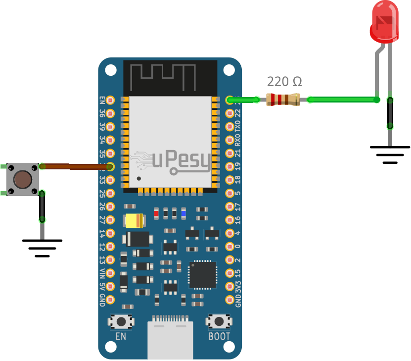
Electrical schematic
Code
Solution
const int buttonPin = 32;
const int ledPin = 23;
int buttonState = 0;
int lastMillis = 0;

void IRAM_ATTR function_ISR() {
 if(millis() - lastMillis > 10){ // Software debouncing buton
         ets_printf("ISR triggered\n");
         buttonState = !buttonState;
         digitalWrite(ledPin,buttonState);
 }
 lastMillis = millis();
}

void setup() {
 Serial.begin(115200);
 pinMode(buttonPin, INPUT_PULLUP);
 pinMode(ledPin,OUTPUT);
 attachInterrupt(buttonPin, function_ISR, CHANGE);
 digitalWrite(ledPin, buttonState);
}

void loop() {
 // Code ...
}