
Using ESP32 I/O with MicroPython
(Updated at 01/23/2023)
The control of the inputs/outputs of the pins (GPIO) is straightforward in MicroPython, thanks to the Pin object of the machine library. You must associate a Pin variable to interact with a “physical” pin on the board. Each physical pin will therefore be represented by a variable (or an object) of type Pin . You just have to use my_pin.a_function() on the “virtual” pin to change the state of the “physical” pin.
You must therefore remember to import this sub-module at the beginning of your Python script:
from machine import Pin
Configure pins as input or output with MicroPython
The configuration of a pin in input/output is done during the creation of an object Pin .
To configure an output pin (for example, for the integrated LED of the ESP32), we create an object Pin specifying the pin number and its output mode (OUT) :
pin_led = Pin(25, mode=Pin.OUT)
If you wish, you can directly set an output voltage when creating the object:
pin_led = Pin(25, mode=Pin.OUT, value=1) # 3.3V on output -> the led will be on
pin_led = Pin(25, mode=Pin.OUT, value=0) # 0V on output -> the led will be off
When creating a Pin object, the output voltage is 0V, and the value is 0.
To configure a pin as input, change the mode in input (IN) when creating the pin.
pin_24 = Pin(24, mode=Pin.IN)
It is possible to specify the type of input you want to have. You can choose between input with a pull-up resistor, a pulldown resistor or without a pull resistor. If you don’t understand these terms, I encourage you to consult the function and usefulness of pull-up and pulldown resistors. We use the optional argument pull , which allows you to choose the type of pull resistor.
pin_24 = Pin(24, mode=Pin.IN, pull=Pin.PULL_DOWN) # Input with a pulldown resistor
pin_24 = Pin(24, mode=Pin.IN, pull=Pin.PULL_UP)   # Input with a pullup resistor (the most used)
Various ways in MicroPython to set or read a voltage
MicroPython offers several functions to impose an output voltage:
Pin.on()andPin.off()Pin.high()andPin.low()Pin.value(value)
The function names are self-explanatory:
pin_led = Pin(25, mode=Pin.OUT)

# Set a voltage of 3.3V at the output (high logic state)
pin_led.on()
pin_led.high()
pin_led.value(1)

# Set a voltage of 0V at the output (low logic state)
pin_led.off()
pin_led.low()
pin_led.value(0)
Note
Choose functions couple that speaks to you the most. For example, .on() | .off() function to turn on LEDs and high() | .low() for a more general case. The function Pin.value() is useful when the value is stored in a variable Pin.value(my_variable) . For example:
pin_led = Pin(2, mode=Pin.OUT)
output_state=1
pin_led.value(output_state) # 3.3V output
output_state=0
pin_led.value(output_state) # 0V output
To read the state of a pin, i.e. 3.3V for a high logic level and 0V for a low logic level, we use the same function Pin.value() without specifying a value.
pin_24 = Pin(24, mode=Pin.IN, pull=Pin.PULL_UP)
pin_24.value() # Returns 1 or 0 depending on the measured voltage
Mini-Project: Turn on the LED when a push button is pressed
To put GPIO pin control into practice, here’s a script that turns on the built-in LED when a push button is pressed. There are two variants of the script: one that uses a digital input with a pull-up resistor and another with a pulldown resistor.
Note
Pull-up resistors are generally used rather than pulldown resistors for digital inputs.
With the internal pull-down resistor of the digital input
Here is the electrical circuit to run the MicroPython script on an ESP32 board.
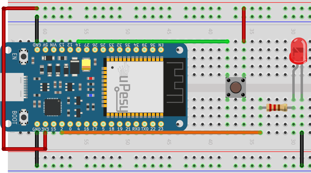
from machine import Pin

pin_button = Pin(14, mode=Pin.IN, pull=Pin.PULL_DOWN)
pin_led    = Pin(2, mode=Pin.OUT)

while True:
    if pin_button.value() == 1:
        pin_led.on()
    else:
        pin_led.off()
With the internal pull-up resistor of the digital input
Here is the electrical schematic associated with the MicroPython script on an ESP32 board. You just have to connect the button to the ground instead of 3.3V.
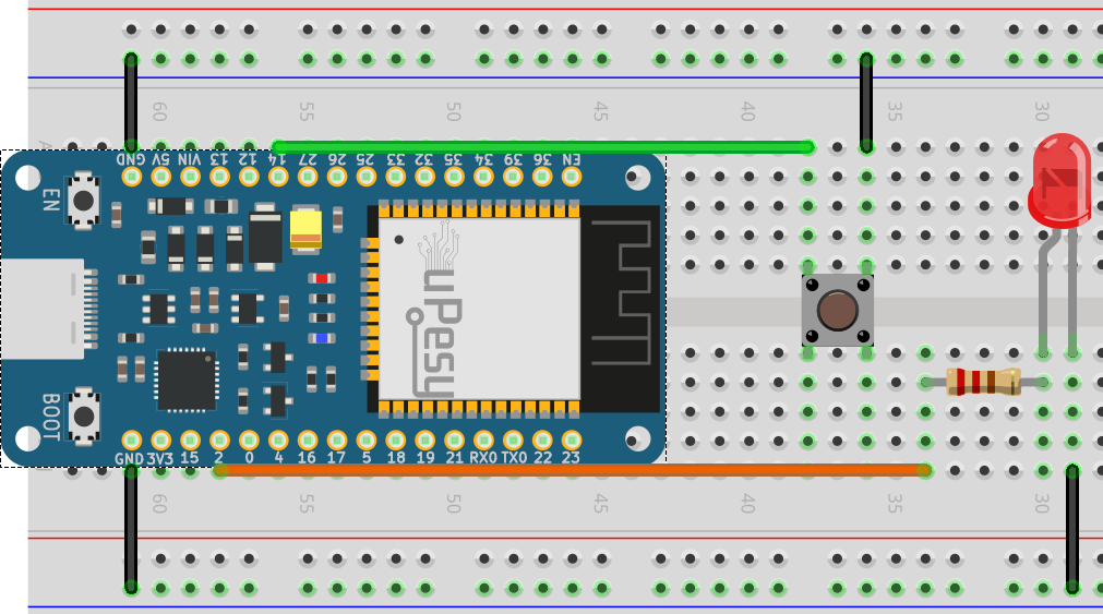
from machine import Pin

pin_button = Pin(14, mode=Pin.IN, pull=Pin.PULL_UP)
pin_led    = Pin(2, mode=Pin.OUT)

while True:
    if not pin_button.value():
        pin_led.on()
    else:
        pin_led.off()
Note
You will notice that we can condense pin_button.value() == 1 by not pin_button.value() in the condition of if .
We can condense the code because a condition if can be written on a single line in Python :
from machine import Pin

pin_button = Pin(14, mode=Pin.IN, pull=Pin.PULL_UP)
pin_led    = Pin(2, mode=Pin.OUT)

while True:
    pin_led.on() if not pin_button.value() else pin_led.off()
We could simplify the code further by removing the if even if we lose clarity.
from machine import Pin

pin_button = Pin(14, mode=Pin.IN, pull=Pin.PULL_UP)
pin_led    = Pin(2, mode=Pin.OUT)

while True:
    pin_led.value(not pin_button.value())
Note
These minor optimizations can be crucial if you want to run the code as quickly as possible because MicroPython is very slow compared to C/C++ language.