
uPesy ESP32 Wroom DevKit v2
(Updated at 01/20/2023)
See also
If you have just received a uPesy ESP32 board, look at the quick start guide if you haven’t already done so.
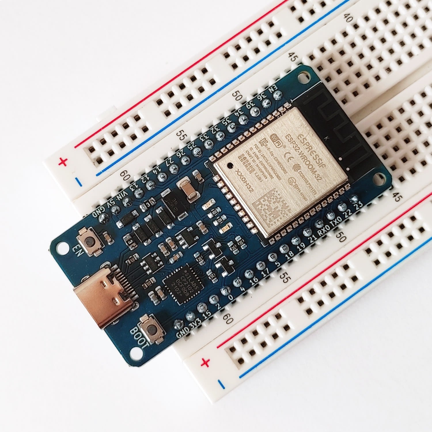
Here is the technical documentation of the board uPesy ESP32 WROOM DevKit . The board is based on an ESP32 module and can be easily put on a breadboard. It is wider than most other ESP32 boards. Y**ou can access the pins on both sides of the board** to connect wires.
Pinout
Each pin of the uPesy board is identified by a number GPIOxx This number allows one to know a particular pin’s functionalities. The pinout of a board corresponds to a diagram that summarizes the functionality of all the pins. Here below are two versions of the pinouts of the board uPesy Wroom DevKit :
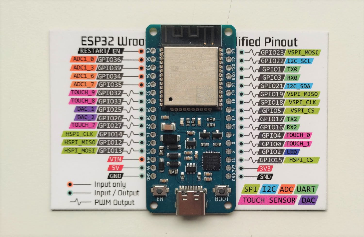
A simplified version that you also have in paper form with the board will help you familiarize yourself with the pins during your first electronic circuits.
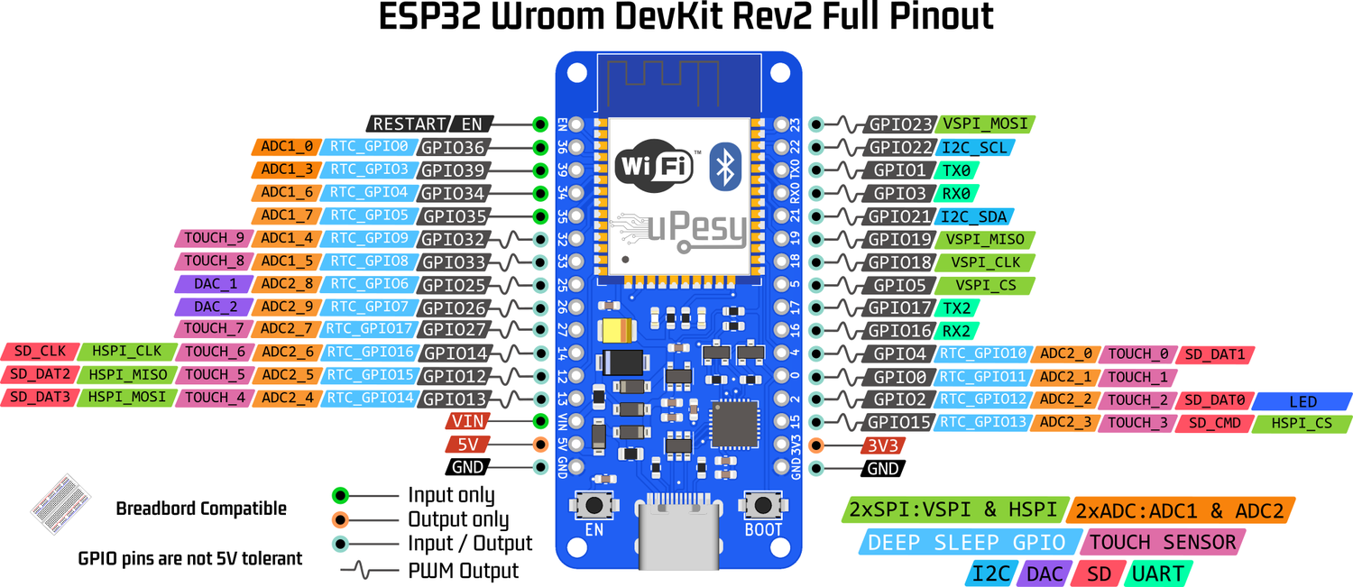
A version contains the majority of the features of each pin.
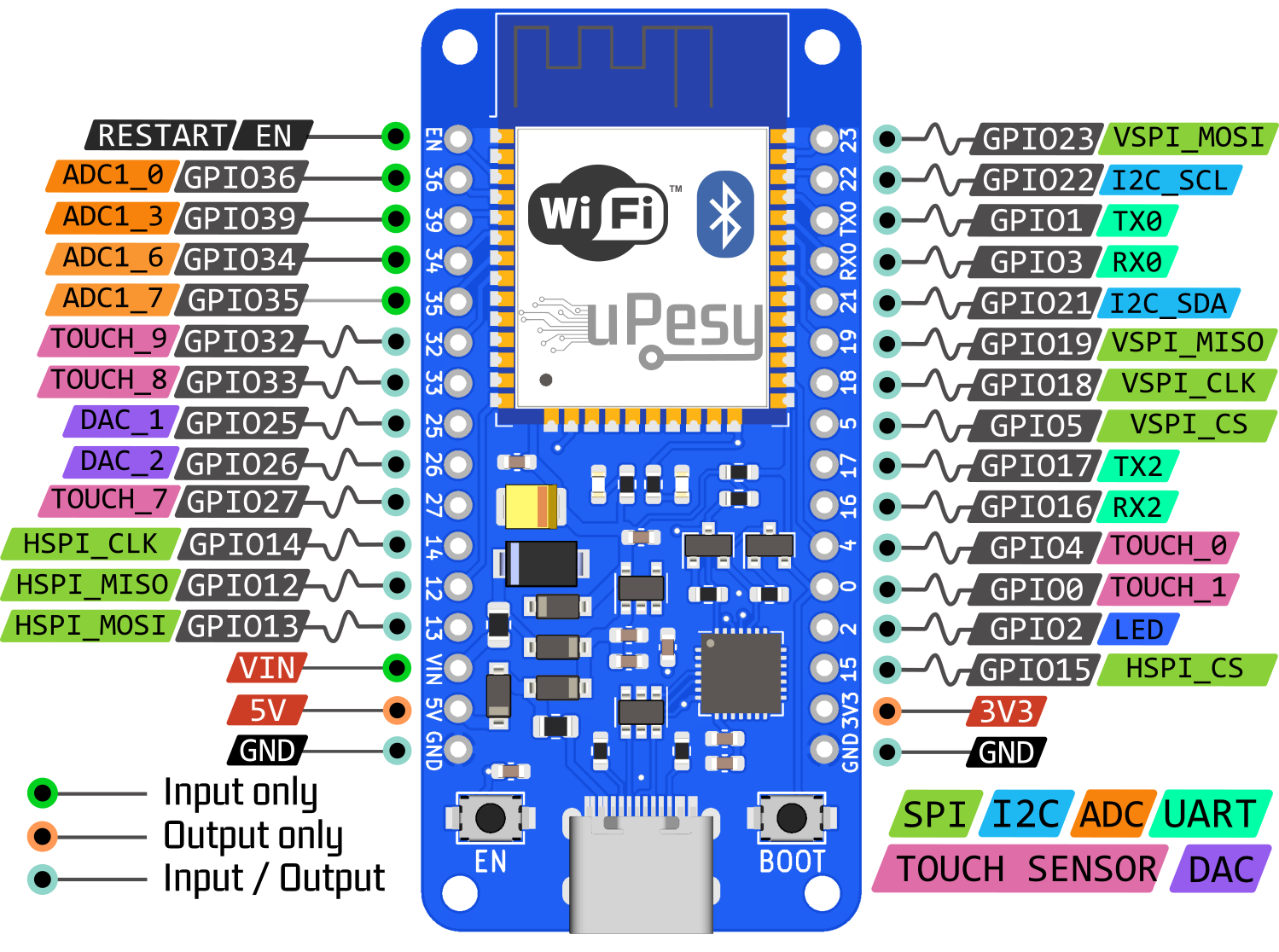
Simplified version
This version, adapted for beginners, presents the main features of the pins.
Note
You can put the ESP32 on the paper sheet to help locate the pins better. 😉
Full version
Note
The pins 36, 39, 34, and 35 pins GPIO36, GPIO39, GPIO34, and GPIO35 can only be used as**input.** They don’t have internal pullup resistors either (You can’t use pinMode(36, INPUT_PULLUP) ).
I would like to invite you to consult the page on the detailed operation of the ESP32 pins for more information.
Details on pin numbers
You will notice that the pins are numbered out of order, unlike the Arduino boards. It will be necessary to refer to the pinout to know the pin number and not deduce it from the position of the pin.
There is a link between the Arduino keywords and the ESP32 pins. The connection is between the keywords and the pins of the ESP32, not between the Arduino and the pins of the ESP32. However, this association is incomplete and often a source of errors. It is therefore not recommended to use it, but it can be helpful to know it to adapt more easily a code initially written for an Arduino to an ESP32.
Here is the link when chosen as the type of board ESP32 Dev Module or DOIT ESP32 DEVKIT V1
Keywords |
Arduino Uno Pin |
ESP32 Pin |
|---|---|---|
|
13 |
2 |
|
0 |
3 |
|
1 |
1 |
|
A4 |
21 |
|
A5 |
22 |
|
10 |
5 |
|
11 |
23 |
|
12 |
19 |
|
13 |
18 |
|
A0 |
36 |
|
A3 |
39 |
|
A4 |
32 |
|
A5 |
33 |
|
25 |
|
|
26 |
Tip
Unlike the Arduino, the pin number of the SPI, I2C, I2S, and SD peripherals indicated in the pinout is assigned by default and can be changed . For example, instead of having the SPI on pins 23, 19, 18, and 5 by default, we can put it on pins 32, 33, 25, and 26 if we want.
Features
We can break down the uPesy ESP32 Wroom DevKit board into four main blocks:
The ESP32 module
The USB to UART converter
Power management
The connectivity
ESP32 module
The brain of the board is the ESP32 module. It is a powerful microcontroller made by Espressif. On the uPesy board, a WROOM module is used: it contains an ESP32 chip and an elementary circuit to make it operate.
Here are links to the manufacturer’s datasheet:
USB/UART converter
This converter plays the role of an “interpreter” between the computer and the ESP32 module so they can communicate together. A CP2102 chip from Silicon Labs is used for this task. It is natively supported by Windows, macOS and Linux. There is, therefore, no need to install any particular driver.
Note
If you get the error “A fatal error occurred: Failed to connect to ESP32: Timed out waiting for packet header”, you can try to add a 10 µF capacitor between the pin EN and GND . Otherwise, you will have to use the manual solution described below.
Power management
This section of the board is responsible for power management. It contains, among other things, a 3.3V voltage regulator and protection. Its operation will be detailed in the Use section.
Connectivity
The USB-C connector of the board allows for communication with the computer. It will allow uploading a program to send messages.
Note
Please make sure you use a USB cable that allows data to pass through, not just for charging a device.
The two buttons, EN and BOOT of the board allow control of the state of the ESP32:
EN: This button, also called RESET, is used to restart the ESP32 forcefully
BOOT: Using this button alone is not very useful. It acts on the behavior of the ESP32 during the boot process.
These buttons can manually put the ESP32 in FLASH mode, which allows loading a new program on the ESP32. Usually, the ESP32 automatically goes into this mode when the upload is done via USB with the CP2102 converter.
Tip
It’s the backup solution when you can’t remove the A fatal error occurred: Failed to connect to ESP32: Timed out waiting for packet header
When :
Connecting........_____....._____....._____....._____....._____....._____....._____....._____....._____....._____
Here is the combination to produce :
Usage
Voltage tolerance of the pins
The ESP32 is a microcontroller that works in 3.3V. The logic levels are, therefore, 0 and 3.3V and not 0 and 5V. That is to say that the output voltage of the GPIO pins is 3.3V, and the input voltage must not exceed 3.3V. The GPIO pins are not designed to have logic levels of 5V .
The voltage measured by the analog-to-digital converter must not exceed 3.3V (and not harmful, of course).
Note
Most modules/sensors can work with 3.3V logic levels, but if this is not the case, you will need level shifters (or at least voltage dividers) to switch from 3.3V to 5V and vice versa.
Warning
Since the ESP32 was not designed to receive 5V on these GPIO pins, you can damage the ESP32 pins if they are exposed to this voltage for too long.
Power supply for the uPesy board
Note
The information given below is only valid for this uPesy board
When the board is powered, a red LED lights up. There are several ways to power the uPesy ESP32 Wroom DevKit board:
The easiest way is by USB in 5V, connecting the board to a computer or an external battery (power bank). You can then use the 5V and 3.3V pins to power an electronic circuit.
Note
The voltage of the 5V pin comes only from the USB.
You can also supply the board directly on the pin \(V_{IN}\) with an external power supply. It would help if you remembered to connect the power supply’s ground to the board’s GND pin. There is no 5V voltage on pin 5V, and only 3.3V is available on pin 3V3.
Warning
The input voltage on the \(V_{IN}\) pin must be between 3.6 and 7V maximum . A voltage of around 5V is optimal.
You can also use the first two methods at the same time. This means having an external power supply connected to the \(V_{IN}\) pin and the board connected to the computer (the two grounds must be attached) . This is very convenient to talk to the Arduino IDE serial monitor while having the ESP32 powered by another external electronic circuit. The operation is as follows:
If \(V_{IN}\) < \(V_{USB}\) with \(V_{USB}=5V\) , then it is the USB that will mainly power the ESP32.
If \(V_{IN}\) > \(V_{USB}\) if the ESP32 is not connected to the external power supply, then the external power supply will be used primarily to power the ESP32.
Warning
In case of error, it is also necessary to remain cautious in this power supply mode to avoid irreversible damage to the ESP32 board, the computer’s USB port, and the external power supply. This operation is usually safe on the uPesy board thanks to a protection circuit that prevents reverse power supply currents. Unfortunately, this is not the case for all ESP32 boards.
Integrated protections
The board uPesy ESP32 Wroom DevKit has a protective battery to avoid damaging it. So that you know, these protections are insufficient to prevent all possible handling errors: the board is not unbreakable.
The board includes the following protections:
Electrostatic discharge protection on the USB port
Short circuit protection on the rail \(V_{IN}\) , 5V and 3.3V. Auto-resetting thermal fuses rated for 350 mA are used on the \(V_{IN}\) and 5V. It is, therefore, necessary to avoid drawing too much current on the board. Otherwise, they may be triggered. They are automatically activated and deactivated (polyfuse).
Warning
Therefore, you should avoid connecting many motors to the power pins.
Protections against current injections on pins 5V and 3V3 to avoid inadvertently injecting a current on these power supply pins.
Warning
You can’t supply the ESP32 board directly with 3.3V on pin 3V3.
Overvoltage protection on the pin \(V_{IN}\) : a passive circuit limits the voltage \(V_{IN}\) ; however, the excess will dissipate as heat and eventually trip the self-resetting thermal fuse.
Reverse polarity protection between \(V_{IN}\) and GND.
Tip
Generally speaking, if the integrated red LED does not light up when you power up the board, there is a power supply issue: you should quickly disconnect the board to avoid damaging it and the power supply itself.
Available resources
3D model (in
.wrl) https://github.com/uPesy/kicad_lib_upesy/raw/master/assets/step_model/upesy_esp32_wroom.wrlPlan with dimensions https://github.com/uPesy/kicad_lib_upesy/raw/master/assets/drawing/upesy_esp32_wroom_devkit_dimension.pdf
Fritzing library https://github.com/uPesy/fritzing_lib_upesy/raw/master/devkit_boards/uPesy ESP32 Wroom DevKit v2.fzpz
KiCad Library https://github.com/uPesy/kicad_lib_upesy