
uPesy ESP32 Wroom DevKit
(Updated at 11/29/2022)
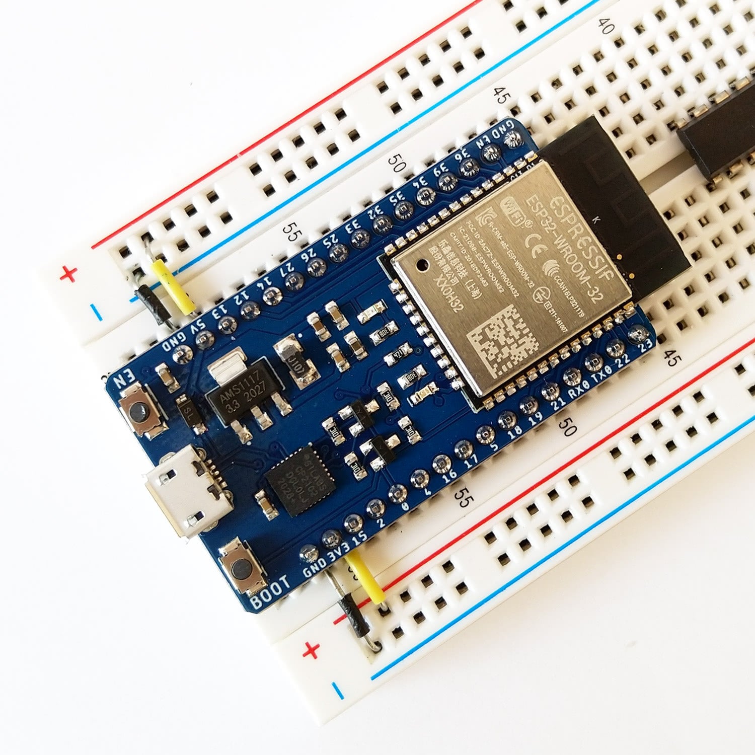
The board uPesy ESP32 WROOM DevKit is based on an ESP32. This board can be put on a breadboard easily because the two sides of the board are accessible to put wires on the breadboard.
Pinout
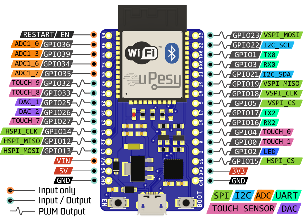
Simplified version
This version, adapted for beginners, presents the main features of boards.
Full version
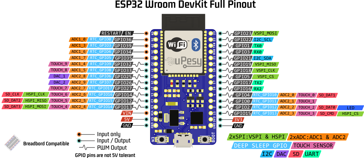
Note
The pins 36, 39, 34, 35 pins GPIO36, GPIO39, GPIO34 and GPIO35, can be used only in input. They don’t have internal pullup resistors either (You can’t use pinMode(36, INPUT_PULLUP) ).
There is a link between the Arduino keywords and the ESP32 pins. The link is between the keywords and the pins of the ESP32 and not between the pins of the Arduino and the pins of the ESP32. However, this link is a source of errors because it is specific to each board (even if globally, it is almost the same for all boards), and it is not complete: only some pins are supported. It is, therefore, not recommended to use it, especially since it is confusing. Still, it can be helpful to adjust a code initially written for an Arduino to an ESP32.
Here is the link when chosen as the type of board ESP32 Dev Module or DOIT ESP32 DEVKIT V1
Keywords |
Arduino Uno Pin |
ESP32 Pin |
|---|---|---|
|
13 |
2 |
|
0 |
3 |
|
1 |
1 |
|
A4 |
21 |
|
A5 |
22 |
|
10 |
5 |
|
11 |
23 |
|
12 |
19 |
|
13 |
18 |
|
A0 |
36 |
|
A3 |
39 |
|
A4 |
32 |
|
A5 |
33 |
|
25 |
|
|
26 |
Tip
Unlike the Arduino, the pin number of the SPI, I2C, I2S, and SD peripherals indicated in the pinout is assigned by default and can be changed. For example, instead of choosing the SPI VSPI on pins 23, 19, 18, and 5, you can put it on pins 32, 33, 25, and 26. A detailed explanation of the pins and peripherals of the ESP32 is available (ESP32 Pinout).
Features
The technical characteristics of the board are as follows:
Processor: Xtensa Dual-Core 32-bit LX6 clocked at up to 240 MHz
Wi-Fi (802.11b/g/n) and Bluetooth 4.2 / BLE
RAM 520 KB of internal SRAM
4 Mb of Flash (external)
Different states to limit power consumption (Modem Sleep, Light Sleep, Deep Sleep, Hibernation)
Hardware cryptographic acceleration for AES, RSA, SHA2
Recommendations for use
Tension tolerance of the pins
The ESP32 is a microcontroller that works in 3.3V. The logic levels are, therefore, 0 and 3.3V and not 0 and 5V. That is to say that the output voltage of the GPIO pins is 3.3V, and the input voltage must not exceed 3.3V. The GPIO pins are not designed to have logic levels of 5V .
The voltage measured by the analog-to-digital converter must not exceed 3.3V (and not harmful, of course).
Note
Most modules/sensors can work with 3.3V logic levels, but if not, you will need level shifters (or possibly voltage dividers) to switch from 3.3V to 5V and vice versa.
Warning
Most modules/sensors can work with 3.3V logic levels, but if not, you will need level shifters (or possibly voltage dividers) to switch from 3.3V to 5V and vice versa.
Power supply for the uPesy board
There are several ways to power the uPesy ESP32 Wroom DevKit board:
The easiest way is by USB in 5V, connecting the board to a computer or an external battery (power bank). You can then use the 5V and 3.3V pins to power an electronic assembly. The red LED on the board lights up as soon as the power is turned on.
We can also supply the board directly by imposing a voltage of 5V on the pin VIN. The voltage on pin 5V is the voltage of the external power supply; by connecting the power supply’s ground to pin GND. The voltage on the 5V pin is that of the external power supply, and the voltage on the 3.3V pin is 3.3V.
Warning
The input voltage on the VIN pin must be between 4.5 and 9V to avoid overheating (and potentially destroying) the 3.3V regulator of the board.
We can use the two first methods simultaneously to have an external power supply connected to the VIN pin while having the board connected to the computer (the two grounds must be tied) . This is very convenient to talk to the Arduino IDE serial monitor while having the ESP32 powered by another external electronic circuit. The operation is as follows:
If \(V_{IN}\) < \(V_{USB}\) with \(V_{USB}\) =5V, then it is the USB that we will mainly use to power the ESP32.
If \(V_{IN}\) > \(V_{USB}\) if the ESP32 is not connected to the external power supply, then the external power supply will be used primarily to power the ESP32.
Warning
This operation usually is safe on the uPesy board thanks to the two protection diodes, which prevent back current in the power supplies. The vast majority of other ESP32 boards do not have these protections! In case of error, it is also necessary to remain vigilant in this power supply mode to avoid irreversible damage to the ESP32 board, the computer’s USB port, and the external power supply.
We can also directly supply the ESP32 with 3.3V on the 3.3V pin with an external power supply, even if it is not recommended . On the other hand, it will not be possible to use the 5V pin.
Warning
The voltage must be around 3.3 V (3V-3.6V); otherwise, the ESP32 may be damaged or destroyed.