
uPesy ESP32 Wroom Low Power DevKit v1.2
(Updated at 03/16/2023)
See also
If you have just received a uPesy ESP32 Wroom Low Power DevKit board, you should look at the quick start guide if you haven’t already done so.
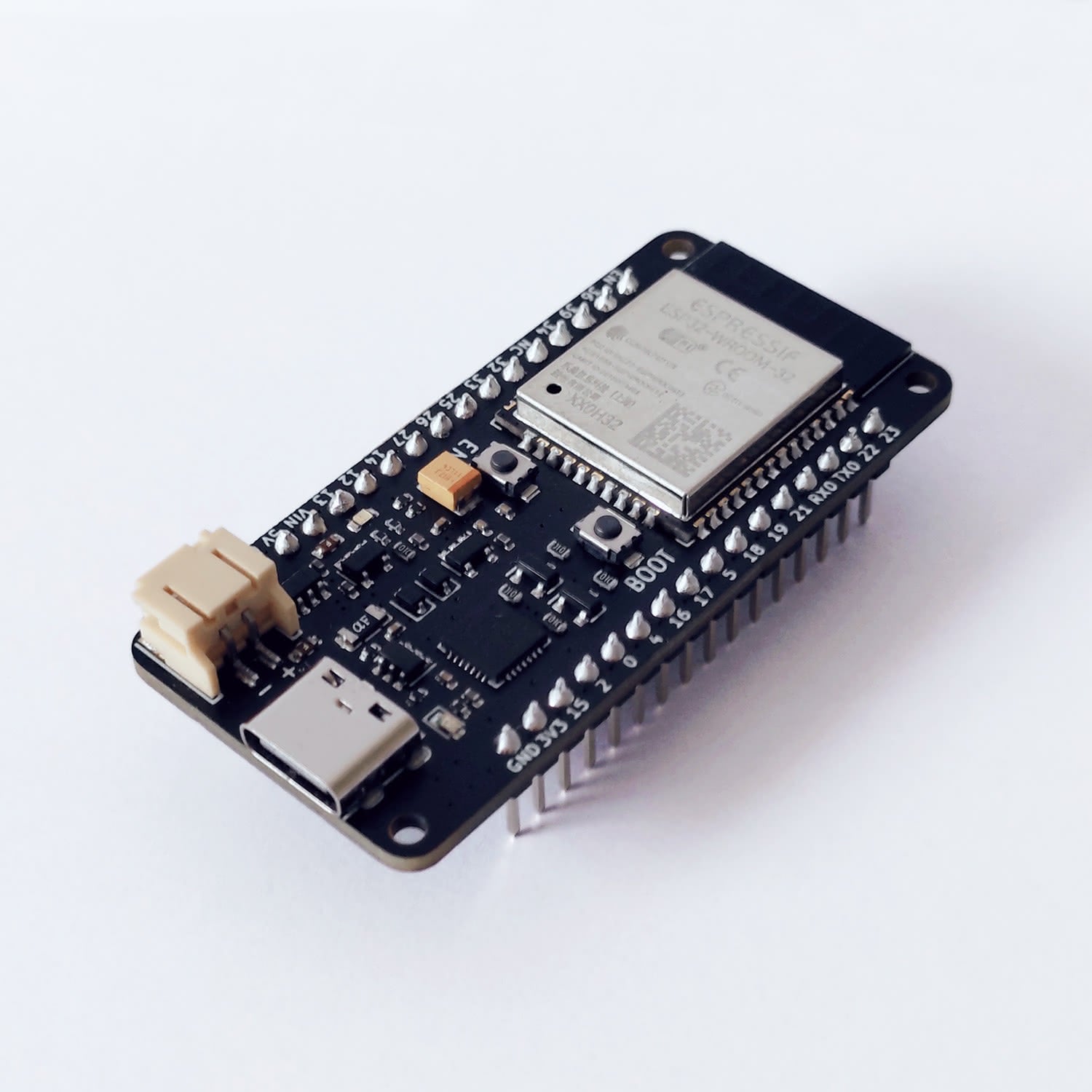
Here is the technical documentation of the uPesy ESP32 WROOM Low Power DevKit board. It is a variant of the uPesy ESP32 Wroom Devkit board optimized to minimize power consumption when the ESP32 is in Deep Sleep mode. Tests performed on different models show a power consumption between 8 and 15µA , which puts it at the top of low-power ESP32 boards in Deep Sleep mode.
On some boards, the consumption in Deep Sleep mode is only 9µA!
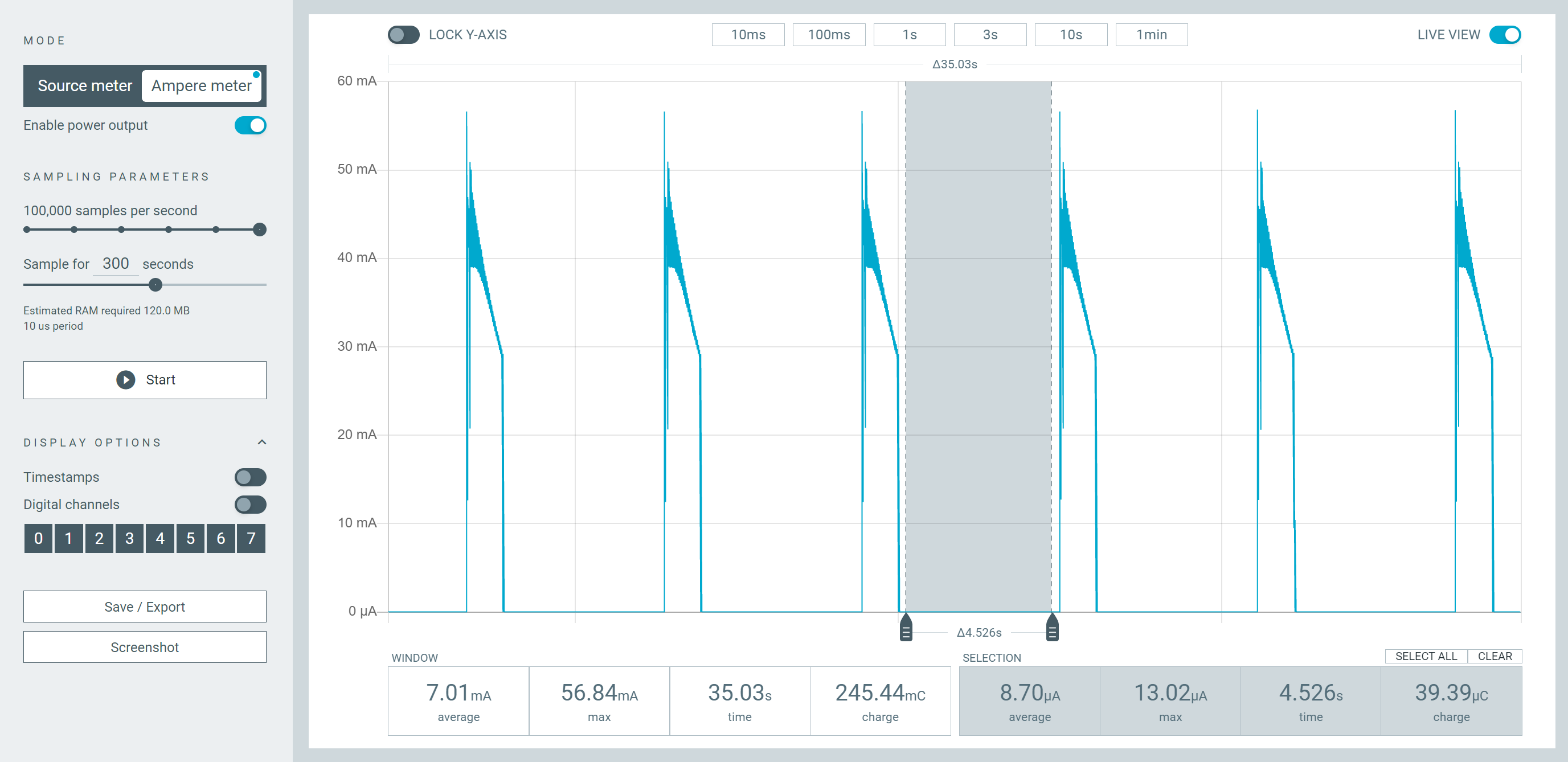
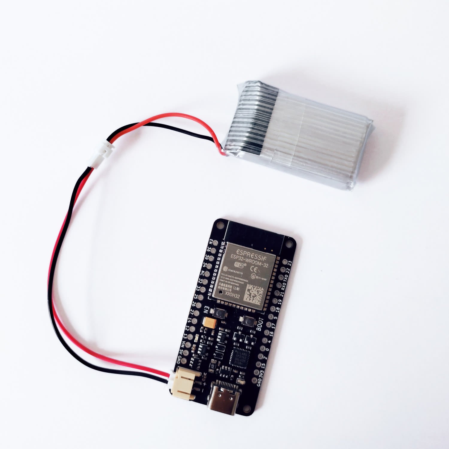
Average current measurement when the ESP32 is in Deep Sleep on a battery
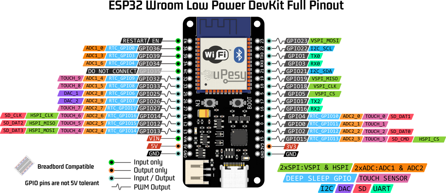
Pinout
The pinout is very similar to the other uPesy ESP32 boards. To remind you, each pin on the uPesy board is identified by a number GPIOxx which lets you know its functionalities. You will receive a sheet of paper on the board with the essential information. Here is the complete version:
Note
Pins 36, 39, and 34, namely pins GPIO36, GPIO39, and GPIO34, can only be used as input only in input. They do not have internal pullup resistors either. You can’t use pinMode(36, INPUT_PULLUP) .
Warning
Unlike the uPesy Wroom DevKit board, you cannot use the GPIO35 pin because it is used to measure the input voltage of the battery.
Warning
There is no blue LED on the GPIO2 pin either!
If you are not comfortable with the GPIO pins of the ESP32, please read the documentation of the basic ESP32 board from uPesy, then complete it by reading the detailed operation of the ESP32 pins .
The connector for the external battery is type JST PH 2.0 (with a 2 mm pitch)
Features
The uPesy ESP32 WROOM Low Power DevKit board can be broken down into four main blocks:
The ESP32 module
The USB to UART converter
Power management
The connectivity
ESP32 module
The brain of the board is the ESP32: a powerful microcontroller made by Espressif . A WROOM module is used (as suggested in the board name 🤔). It contains an ESP32 chip and a primary circuit to run it.
You will find all the technical information you need in the manufacturer’s datasheets:
USB/UART converter
Since the ESP32 does not understand the USB protocol, a Silicon Labs chip, the CP2102 acts as a translator with the computer, he’s natively supported by Windows, macOS and Linux, so there is no need to install an additional driver, as would be with a CH340G.
Note
If you encounter the error “A fatal error occurred: Failed to connect to ESP32: Timed out waiting for packet header”, you can try to add a 10 µF capacitor between the pin EN and GND . Otherwise, you will have to use the manual solution described below.
Power management
This section of the board is responsible for power management. It contains, among other things, a 3.3V voltage regulator and protection. Its operation will be described in detail in the next section.
Connectivity
The USB-C connector allows powers the board and communicates with the computer. It will enable the user to upload a program and print messages in the console …
Note
Please make sure you use a USB cable that allows data to pass through, not just for charging a device.
The two buttons EN and BOOT of the board allow to control the state of the ESP32:
EN: This button, sometimes called RESET, is used to restart the ESP32 forcefully.BOOT: This button alone has no effect when the ESP32 is already turned on. It acts on its behavior during the boot process.
These two buttons can manually put the ESP32 in FLASH mode, which allows loading a new program on the ESP32. Usually, the ESP32 automatically goes into this mode when the upload is done via USB with the CP2102 converter.
Tip
This is usually the working solution when you cannot resolve the error “a fatal error occurred: Failed to connect to ESP32: Timed out waiting for packet header.”
To do this, when the connection stage with the ESP32 reaches the:
Connecting........_____....._____....._____....._____....._____....._____....._____....._____....._____....._____
The following combination is required:
Usage
Voltage tolerance of the pins
The ESP32 is a microcontroller that works in 3.3V. The logic levels are, therefore, 0 and 3.3V and not 0 and 5V. That is to say that the output voltage of the GPIO pins is 3.3V, and the input voltage must not exceed 3.3V. The GPIO pins are not designed to have logic levels of 5V .
The voltage measured by the analog-to-digital converter must not exceed 3.3V (and not negative, of course).
Note
Most modules/sensors can work with 3.3V logic levels, but if this is not the case, you will need level shifters (or at least voltage dividers) to switch from 3.3V to 5V and vice versa.
Warning
Since the ESP32 was not designed to receive 5V on these GPIO pins, you can damage the ESP32 pins if they are exposed to this voltage for too long.
Different Power Mode
There are three ways to power the ESP32 Low Power board. Two are optimized for low current consumption:
Via USB (\(V_{BUS}\) ): The board is connected via its USB-C connector to a computer or a suitable phone charger. A red LED lights up as soon as the power is turned on. This power supply mode is not optimized for the consumption of current.
Via an external battery (\(V_{BAT}\) ): We connect a Lithium-ion/LiPo battery of 3.7V on the JST2.0 connector. If we combine the USB simultaneously, the board charges the battery. This power supply mode is optimized for the current consumption: the consumption will be <15µA in Deep Sleep.
Via an external power supply (\(V_{IN}\) ): We connect on the pin \(V_{IN}\) of the ESP32 board an external power supply with a voltage between 3.5V and 7V maximum . This power supply mode is optimized for the current consumption: the consumption will be <15µA in Deep Sleep.
Note
No LED lights up when the board is powered in the optimized power supply modes . Indeed, even a simple LED consumes a few mA.
Power supply modes operation
Since there are several possible supply paths, here are some additional explanations of their relations:
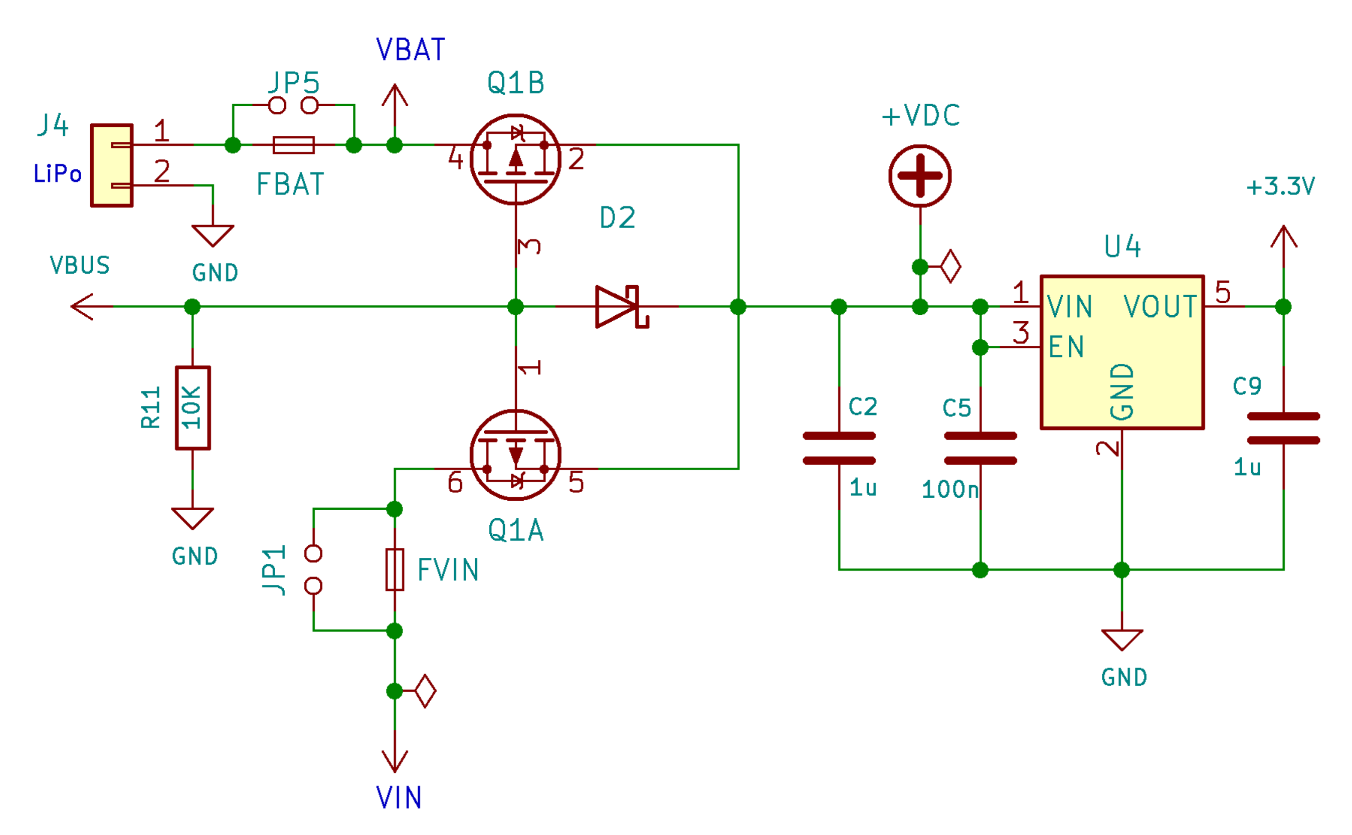
As soon as the board is powered via USB, any external power supply connected to the \(V_{IN}\) or a battery connected to the connector will be disabled. The electrical power comes only from the USB.
Tip
You can safely have the board powered by USB while having an external power supply or a battery connected.
If a battery is connected and partially discharged, the integrated charger of the board will start to recharge it: and a blue LED will light up.
Note
Note that there is a 5V voltage on the 5V pin of the board only when the board is connected via USB.
The battery connector is directly connected to the \(V_{IN}\) ; therefore, if you connect a battery, the battery voltage will also be available on the \(V_{IN}\) .
Warning
You must never use an external power supply and a battery simultaneously ! Otherwise, the battery and your external power supply may be damaged or destroyed.
The battery connector is also connected to the charging circuit.
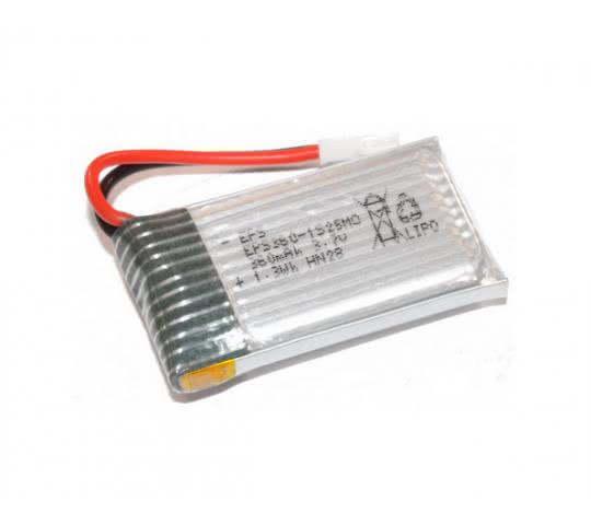
Battery type to use
The battery must be compatible with the integrated charger of the uPesy board. The charger is IC an MCP73831 from MicroChip , which allows recharging Li-Ion/Li-Polymer batteries of a single cell of 3.7V (or 4.2V when the battery is fully charged).
They are widely used on mobile devices.
Tip
For those in the RC model world, this corresponds to a lipo 1S battery.
Warning
You must not use batteries containing several cells (2S, 3S, …)
Warning
Do not use AAA, LR3, or LR6 batteries, either rechargeable or not, on the rail \(V_{BAT}\) .
The battery’s capacity will depend on your application and how long you need to recharge the battery. A capacity of 1000mAh or 2000mAh will be more than enough in most cases.
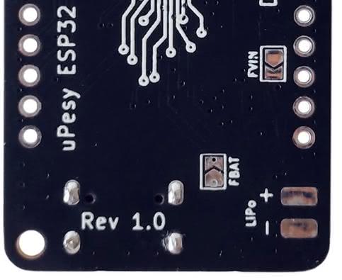
The other important point is to check that the polarity of your battery matches that of the board.
Warning
There is no reverse polarity protection at the battery connector.
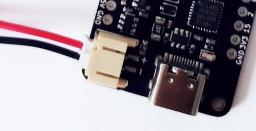
Please take a look at the picture above. To check the polarity of the 3.7V battery, the red wire must be plugged on the “+” side.
Tip
You can easily swap the two cables of the connector if the polarity is incorrect.
Here are examples of batteries compatible with the uPesy board:
https://www.amazon.com/dp/B087LTZW61 [JST 1.25 connector]
https://www.amazon.com/dp/B082152887 [reversed polarity]
The battery charging process
Recharging a battery already connected to the JST connector is done as follows :
The battery no longer powers the board when a USB cable is connected. It is the USB power supply that will both power the board and charge the battery in addition.
Note
It’s better to connect the battery first, then the USB. Sometimes, on the other way, the charger does not start charging.
The blue LED should light up. This LED will only light up while the battery is being charged.
As long as the blue LED is on, the battery is charging.
When this LED is off, the battery is fully charged.
The USB cable can be disconnected, and the battery will power the ESP32 again.
The maximum charging current is limited to 500 mA.
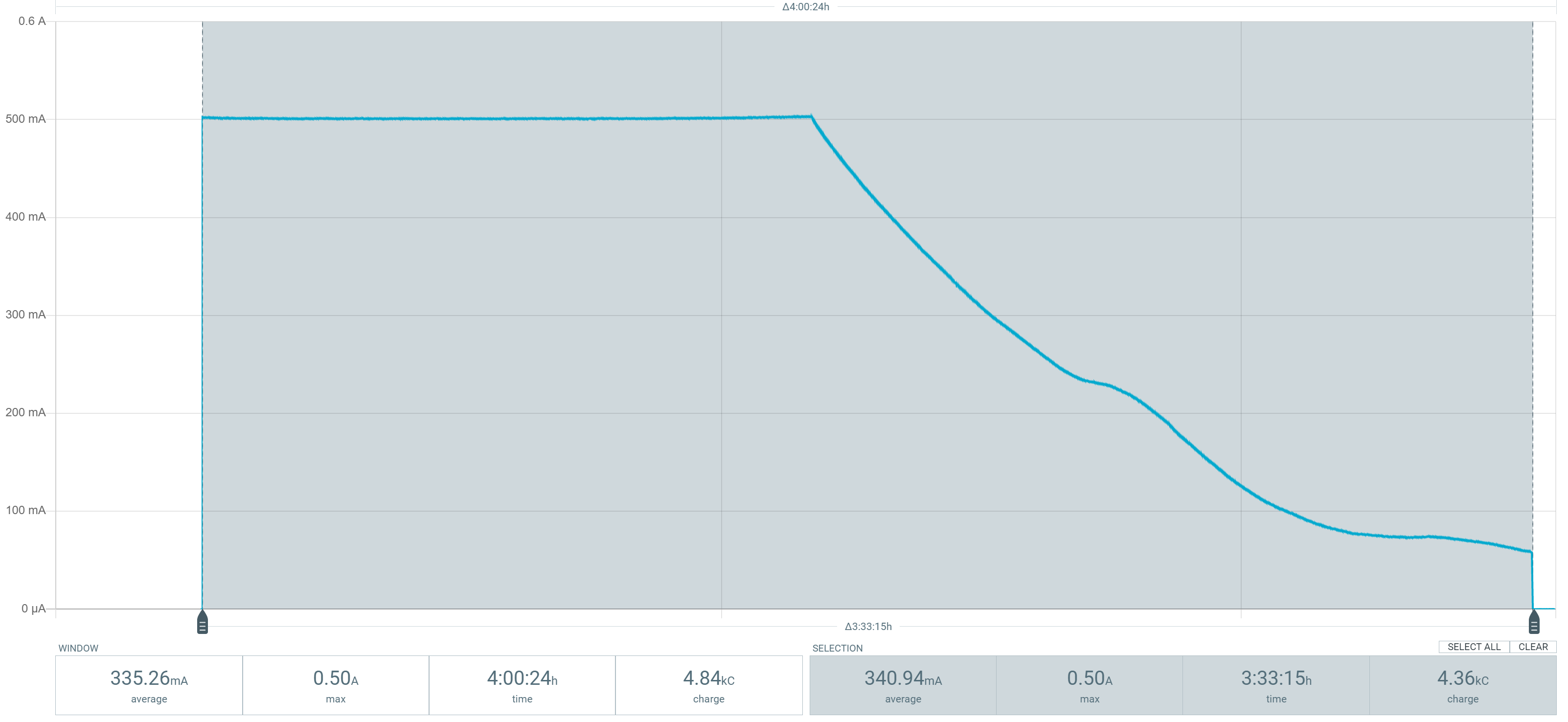
For an empty 1000mAh battery, the total charge time is around 3h30. 70% of the battery is recharged in 1h30, the remaining 30% in 2h. It can be relevant for a “fast” charge to stop the charge at 70% when the charge current starts to decrease. Unfortunately, this type of charger does not indicate this mode change: the blue LED will only be turned off at the end of the cycle. However, you can implement a counter in the ESP32 that notifies the user after 1h30 that the battery is charged at around 70%.
Note
The complete charging procedure is available in the MCP73831 charger datasheet .
How to know the battery discharge from the code
With a Li-Ion/Li-Polymer battery, we can estimate its remaining capacity based on its voltage. The board integrates a voltage divider bridge, connected to the pin GPIO35 , which divides by two the voltage \(V_{DC}\)
Warning
This method only works when the board is battery powered. The returned voltage will be wrong if the USB is connected at the same time to recharge the battery.
We can therefore know either the voltage of the battery \(V_{BAT}\) , of an external power supply \(V_{IN}\) or also of the USB \(V_{BUS}\) with the following formula :
The ratio is \(1.435\) . The following Arduino code is used to measure the battery voltage :
void setup() {
  pinMode(35, INPUT); // You should set the input pin
  Serial.begin(115200);
}

void loop() {
  float v_mes = analogRead(35);
  float v_dc = 1.435*(v_mes/4095)*3.3;
  Serial.println(v_dc);
  delay(100);
}
For your information, in theory, if we apply the classical formula, the ratio of the dividing bridge should be equal to \(1.37\) and not \(1.435\) :
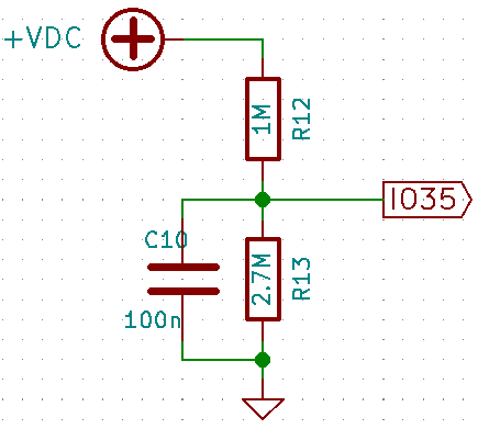
But in practice, since the primary current of the divider bridge is very low given the values of the resistors (1 and 2.7MΩ), we can no longer neglect the leakage current to the pin GPIO35 . This is the main reason for the difference between the values. If we consider the resistors’ tolerance (1%), your ratio can be slightly different by a few hundredths.
Built-in protections
The uPesy ESP32 WROOM Low Power DevKit board has built-in fuses to protect your projects against short circuits :
On the USB rail (\(V_{BUS}\) ), there is a 750mA self-resetting thermal fuse. It turns on and off automatically (a resistor that varies with the temperature, called polyfuse).
Note
When charging a battery, you should avoid drawing too much current on other circuits (on motors, for example) to prevent this fuse tripping.
On each of the rails \(V_{BAT}\) and \(V_{IN}\) there are 750mA non-resettable fuses from LittelFuse \(F_{BAT}\) and \(F_{VIN}\) . If they blow off, you must put in new ones because the board will no longer be powered. Fortunately, there are footprints on the back of the board for this purpose.
Tip
It is also possible to disable these two fuses by making a soldering bridge, whether blown or not. By disabling this security, you must ensure that your power supply (battery or external) has adequate protection against possible short circuits.
There is globally less protection than on the uPesy ESP32 Wroom DevKit board to limit the power consumption as much as possible and thus obtain a very low power consumption in Deep Sleep mode. There is no protection against overvoltage on the rails \(V_{BAT}\) and \(V_{IN}\) or reverse polarity protection on the battery.
Free Ressources files
3D model (in
.wrl): https://github.com/uPesy/kicad_lib_upesy/raw/master/assets/step_model/upesy_esp32_low_power.wrlPlan with dimensions: https://github.com/uPesy/kicad_lib_upesy/raw/master/assets/drawing/upesy_esp32_low_power_devkit_dimension.pdf
Fritzing library: https://github.com/uPesy/fritzing_lib_upesy/raw/master/devkit_boards/uPesy ESP32 Wroom Low Power DevKit v1.fzpz
KiCad Library: https://github.com/uPesy/kicad_lib_upesy
Changelog
v1.2 (February 2023)
Modify the board to be assembled in the uPesy factory (schematic is the same)
Use
0603passive components instead of0402Move the 2 push-buttons
v1.1
Change the maximum current charge from 350mA to 500mA.
Change the fuse’s rating from 500mA to 750mA.
Add a 100nF capacitor for the internal measurement of the battery voltage by the ADC (
GPIO35).Change resistors value on voltage divider for
GPIO35
v1.0
First release