
uPesy ESP32 Wrover DevKit v2.1
(Updated at 03/16/2023)
See also
If you have just received a uPesy ESP32 board Wrover DevKit, I advise you to first look at the quick start guide if you have not already done yet 🙂.
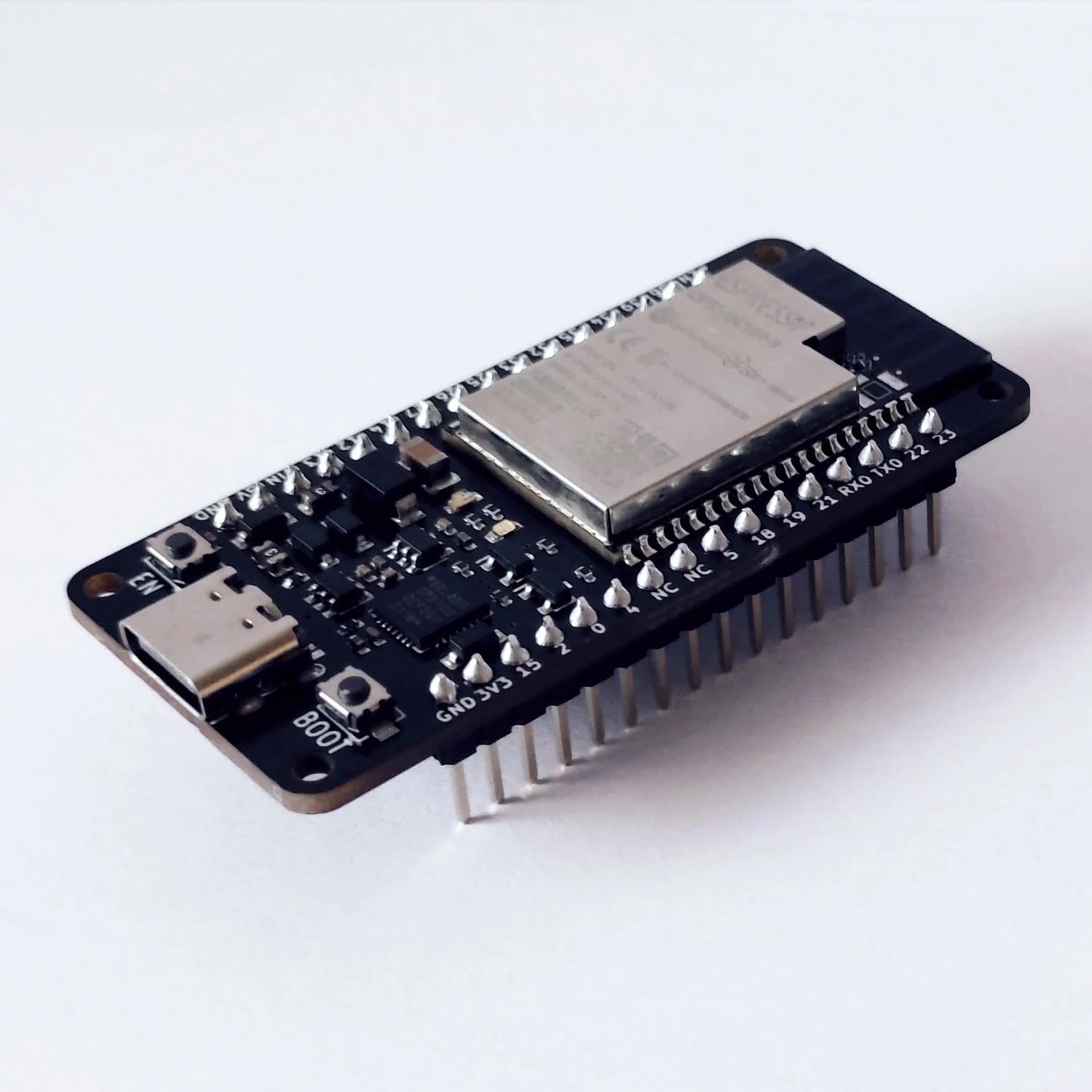
The uPesy ESP32 WROVER DevKit board is based on an ESP32. This board can be put on a breadboard easily because the two sides of the board are accessible to put wires on the breadboard.
Note
The board has an additional 4 MB of RAM. Indeed, most ESP32 boards are based on an ESP32-WROOM-32 module, whereas this board is based on an ESP32-WROVER-B module. The two modules are very similar and are programmed in the same way; the only difference between the 2 is the addition of an external RAM for the ESP32-WROVER-B module.
Tip
For more information, see this page on the operation and use of PSRAM on ESP32.
Pinout
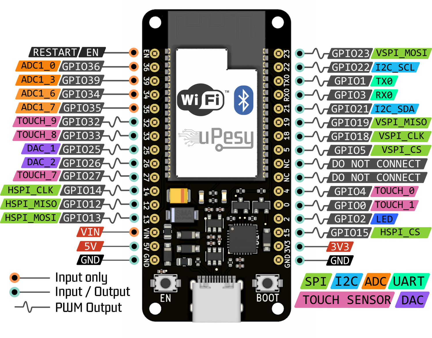
Simplified version
This version, adapted for beginners, presents the main features of the pins.
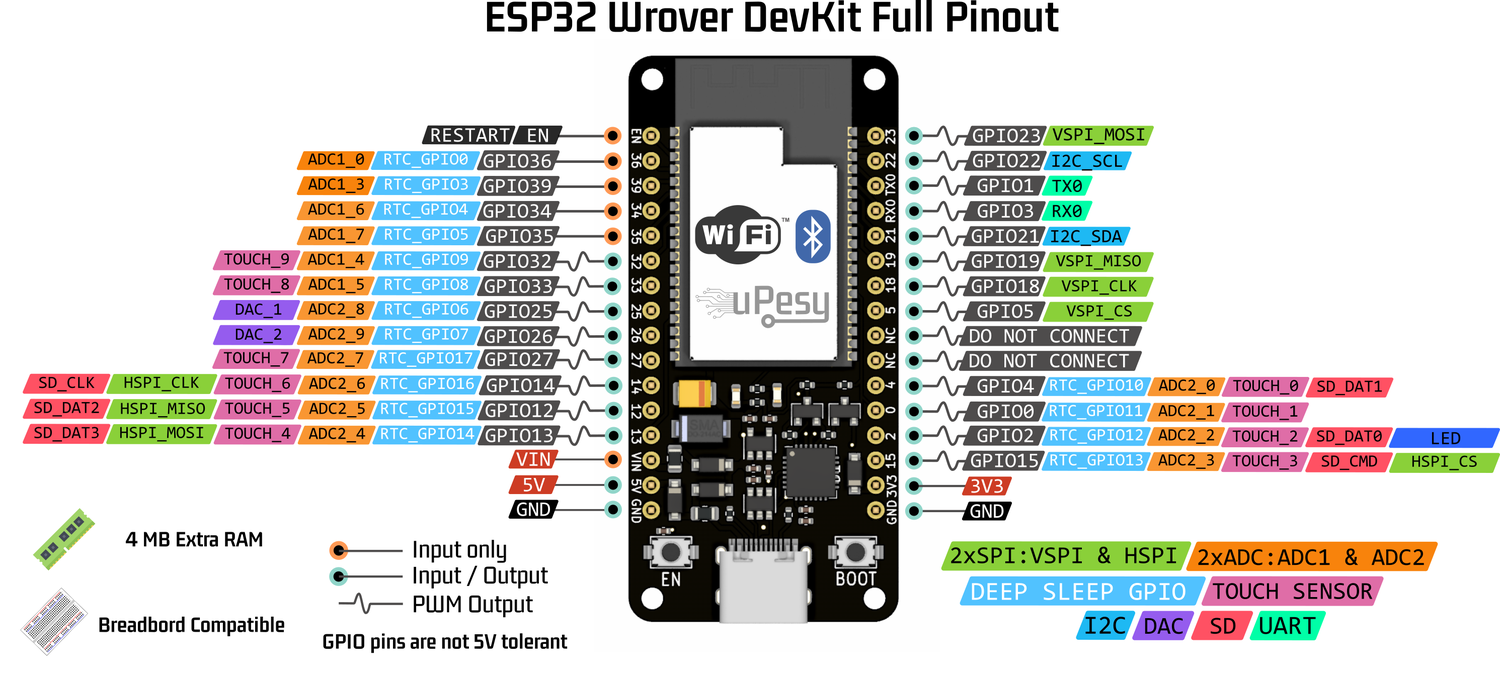
Full version
Note
Pins VP, VN, 34, 35: pins GPIO36, GPIO39, GPIO34, and GPIO35 can only be used as input. They do not have internal pullup resistors either. You cannot use pinMode(36, INPUT_PULLUP) .
Tip
Unlike the Arduino, the pin number of the SPI, I2C, I2S, and SD devices indicated in the pinout is assigned by default and can be changed. For example, instead of choosing VSPI on pins 23, 19, 18, and 5, you can put it on pins 32, 33, 25, and 26.
For more details on the ESP32 pins, I encourage you to read the ESP32 pinout guide .
Features
The technical characteristics of the board are as follows:
CPU : Xtensa Dual-Core 32-bit LX6 240 MHz
Wi-Fi (802.11b/g/n) et Bluetooth 4.2 / BLE
RAM : 520 Ko of inner SRAM et 4 Mo of external PSRAM
16 Mo of Flash (external)
Different modes to limit power consumption (Modem Sleep, Light Sleep, Deep Sleep, Hibernation)
Hardware cryptographic acceleration for AES, RSA, SHA2
Use the external antenna
On the uPesy ESP32 board Wrover DevKit, it is possible to use an external antenna for Wi-Fi instead of the one integrated on the Wrover module. Putting an external antenna increases the gain in transmission and reception of the Wi-Fi signal. The gain is usually defined in dB.
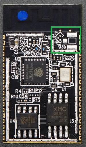
Location of the IPEX connector for an external antenna (in green)
You must solder the 1st generation IPEX connector on the footprint provided for this purpose, located in the green square in the picture above. Once the IPEX connector is soldered on, you can connect a standardized external antenna to it.
Warning
You can use only one antenna at a time.
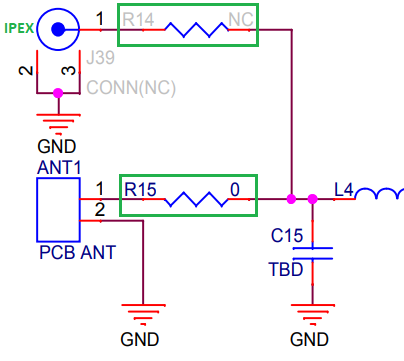
The selection of one antenna over another is made via 0 Ω resistors. By default, the resistor R15 is placed to use the antenna on the PCB, while the resistor R14 is not present. To use the external antenna, you must do the opposite: R14 present, R15 absent. In practice, it is sufficient to rotate the current resistor by 90°.
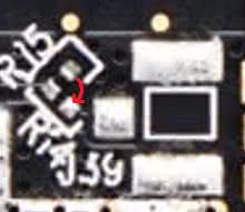
Change the position of the resistor to use the IPEX connector
Tip
A solder bridge can also replace the resistor due to its small size.
Usage recommendations
Pin tolerance
The ESP32 is a microcontroller that operates at 3.3V. The logic levels are therefore 0 and 3.3V and not 0 and 5V. That is to say that the output voltage of the GPIO pins is 3.3V, and the input voltage must not exceed 3.3V. The GPIO pins are not designed to have logic levels of 5V.
Note
Most modules/sensors can work with 3.3V logic levels, but if this is not the case, you will need level shifters (or possibly voltage divider bridges) to switch from 3.3V to 5V and vice versa.
Warning
Since the ESP32 was not designed to receive 5V on these GPIO pins, you can damage the ESP32 pins if they are exposed to this voltage for too long.
The voltage measured by the ADC must not exceed 3.3V (and not negative, of course).
Powering the uPesy board
There are several ways to power the uPesy ESP32 board Wrover DevKit:
The easiest way is by USB in 5V, connecting the board to a computer or an external battery (power bank). We can then use the pins 5V and 3V3 of the board to supply an electronic circuit in 5V and 3.3V, respectively. The regulator of the board generates the 3.3V voltage.
You can also power the board directly on the \(V_{IN}\) pin via an external power supply. You must remember to connect the power supply’s ground to the board’s GND pin. There is no 5V voltage on the 5V pin, and only a 3.3V voltage is available on pin 3V3. Indeed, the 5V voltage comes only from the USB; the board does not have a 5V regulator.
Warning
The input voltage on pin \(V_{IN}\) must be between 3.6 and 7V maximum. A voltage around 5V is optimal.
You can also use the first two methods simultaneously: having an external power supply connected to the \(V_{IN}\) pin while having the board connected to the computer (the two grounds must be attached). This is quite convenient for communicating with the serial monitor of the Arduino IDE while having the ESP32 powered by another external electronic circuit. It functions like so :
If \(V_{IN}\) < \(V_{USB}\) , with \(V_{USB}\) =5V, then it is the USB that will be mainly used to power the ESP32.
If \(V_{IN}\) > \(V_{USB}\) , then it is the external power supply that will be mainly used to power the ESP32.
Warning
You must also be careful with this power supply mode to avoid irreversible damage to the ESP32 board and/or the computer’s USB port and/or the external power supply in case of an error. This operation is usually safe on the uPesy board thanks to a protection circuit that prevents back current in the power supplies. Unfortunately, this is not the case for all ESP32 boards.
Built-in protections
The uPesy ESP32 Wrover Devkit board has a set of protections to avoid damaging it. These protections are insufficient to prevent all possible handling errors: the board is therefore not indestructible.
The board includes the following protections :
Electrostatic discharge protection on the USB port
Short circuit protection on the \(V_{IN}\) , 5V and 3.3V rails: Self-resetting thermal fuses of 350 mA are used on the \(V_{IN}\) and 5V rails. It is important to avoid drawing too much current on the board; otherwise, they may trip. They are automatically activated and deactivated (polyfuse).
Protections against current injections on pins 5V and 3V3 to avoid inadvertently injecting a current on these power supply pins.
Overvoltage protection on \(V_{IN}\) pin: a passive circuit limits the \(V_{IN}\) voltage; however, the excess will be dissipated as heat and eventually trigger the self-resetting thermal fuse.
Protection against polarity inversion between \(V_{IN}\) and GND.
Important
Generally speaking, if the integrated red LED does not light up when the board is powered up, there is a power supply problem: you should quickly disconnect the board to avoid damaging the board and/or the power supply itself.
Available Source Files
3D model (in
.wrl) https://github.com/uPesy/kicad_lib_upesy/raw/master/assets/step_model/upesy_esp32_wrover.wrlPlan with dimensions https://github.com/uPesy/kicad_lib_upesy/raw/master/assets/drawing/upesy_esp32_wrover_devkit_dimension.pdf
Fritzing library https://github.com/uPesy/fritzing_lib_upesy/raw/master/devkit_boards/uPesy ESP32 Wrover DevKit v1.fz
KiCad Library https://github.com/uPesy/kicad_lib_upesy
Changelog
v2.1 (February 2023)
Modifications of the board to be assembled in the uPesy factory
Migrate components to
0603packageReplace the ESP32-WROVER module by the variant with 16MB flash.
v2.0
First version