
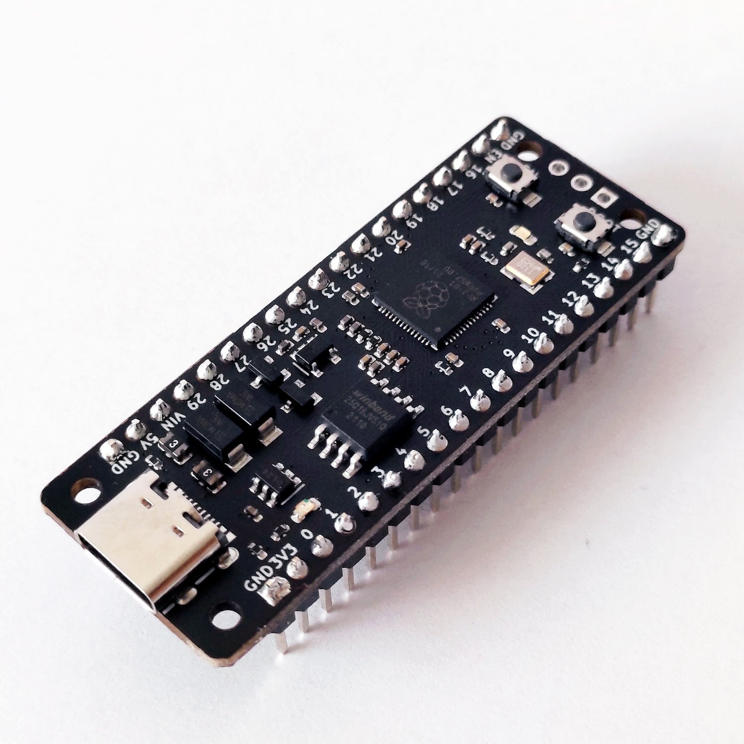
uPesy RP2040 DevKit
(Updated at 11/30/2022)
See also
If you have just received a uPesy RP2040 DevKit board, please take a look at the quick start guide if you haven’t already.
The uPesy RP2040 DevKit board is based on the same RP2040 chip as the Raspberry Pi Pico. For the record, the Raspberry Pi Foundation entered in early 2021 with its Raspberry Pi PICO board. This move surprised everyone, primarily since it is based on the RP2040 microcontroller developed by the Raspberry Pi Foundation.
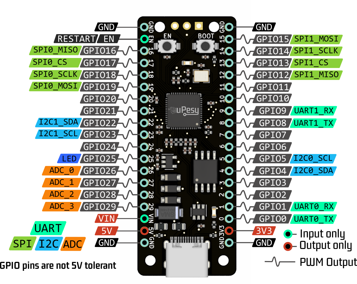
Pinout:
Simplified Pinout version
This version, suitable for beginners, presents the main features of the pins.
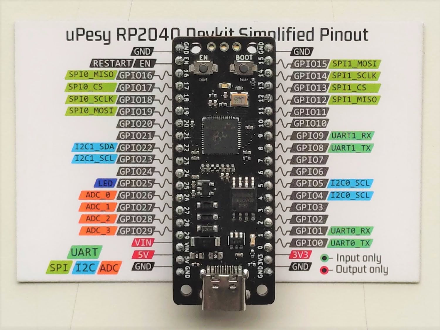
Note
You can put the ESP32 on the paper sheet to help locate the pins better. 😉
Full Pinout version
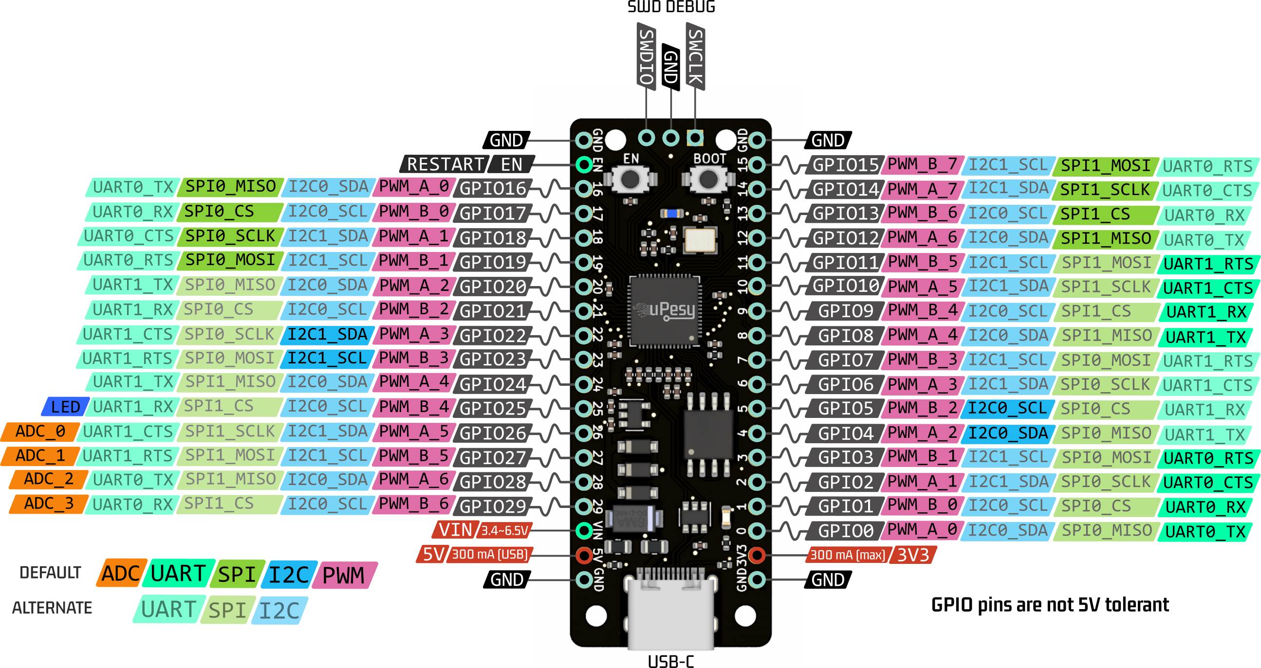
Note
The uPesy RP2040 DevKit board is not pin to pin compatible with the Raspberry Pi Pico.
Features
Here are the technical specifications of the uPesy RP2040 Devkit board: they come mainly from the RP2040 chip designed by Raspberry Pi in the UK.
For their first microcontroller, the performance is impressive:
32-bit dual-core ARM Cortex M0+ microprocessor clocked at up to 133 MHz: Thanks to the two cores, you can run two programs in parallel. With a CPU clock of up to 133 MHz, the uPesy RP2040 board can execute up to 16x more instructions than an Arduino Uno in the same amount of time.
264 KB of SRAM memory and 2 MB of integrated Flash memory. 132 times more RAM and 64 times more Flash memory than on the Arduino Uno.
Native support of USB 1.1: There is no more intermediate chip to communicate between the computer and the microcontroller, unlike Arduino and ESP32. It is, therefore, straightforward to put a compiled program on the uPesy RP2040 board since it is detected as a simple USB key.
The uPesy RP2040 board exposes 30 multifunction GPIO pins, which is four pins more than on the original Pi Pico. Indeed, on the Pi Pico, some pins are used internally on the board: to measure some voltages and manage the power supply, for example. Here, the choice was to expose as many GPIO pins as possible.
Serial peripherals: 2xUART, 2xSPI, 2xI2C, 16 independent PWM channels, 4x12-bit ADC (only 3 analog inputs on the Pi Pico)
Eight state machines on programmable inputs/outputs (PIO) to create custom peripherals. Hardware logic blocks can be configured to have additional peripherals: UART, SPI, I2S, and even a rudimentary VGA driver. These features are for the more advanced.
Several operating modes limit energy consumption.
Note
Processor VS microcontroller
The classic Raspberry Pi boards (RPI 3B+, RPI 4, RPI Zero) are CPU-based boards: they are nano-computers that need an operating system (Linux or Windows) to function. We can use them like a classic computer with GPIO pins to interact with external electronic circuits.
A microcontroller consists of a CPU and many peripherals : RAM, I/O pins, UART bus, SPI, and I2C… The uPesy RP2040 DevKit board is based on the Arduino or the ESP32 on a microcontroller . It has much less computing power but is more reliable, making it easier to interact with GPIO pins (Input/Output) and do low-level programming. There is no OS on it .
Usage recommendations
Voltage tolerance of the pins
The RP2040 is a microcontroller that operates at 3.3V. The logic levels are, therefore, 0 and 3.3V and not 0 and 5V. Thus, the maximum output voltage of the GPIO pins is 3.3V, and the maximum input voltage is also 3.3V.
The voltage measured by the ADC must not exceed 3.3V (and, of course, must not be negative either).
Note
Most modules and sensors can work with 3.3V logic levels, but if this is not the case, you will need level shifters (or possibly voltage divider bridges) to switch from 3.3V to 5V and vice versa.
Warning
Since the RP2040 was not designed to receive 5V on its GPIO pins, it can be damaged if exposed to this voltage for too long. In practice, short exposure to a 5V voltage on its pins will not be fatal, but it may be in the long term. Please be careful.
Power supply for the uPesy RP2040 board
There are several ways to power the uPesy RP2040 DevKit board:
The easiest way is via the 5V USB connector, by connecting the board to a computer or an external battery (power bank). You can then use the 5V and 3.3V pins to power an electronic assembly.
Note
Please remember to take a USB cable to send data to communicate with the computer.
We can also power the board directly by setting a voltage of about 5V on the \(V_{IN}\) pin by an external power supply and by connecting the power supply’s ground to the GND pin. The input voltage on the \(V_{IN}\) pin must be between 3.4V and 6.5V to avoid destroying the 3.3V regulator of the board.
Available source files
3D model (in
.wrl) https://github.com/uPesy/kicad_lib_upesy/raw/master/assets/step_model/upesy_rp2040_devkit.wrlPlan with dimensions https://github.com/uPesy/kicad_lib_upesy/raw/master/assets/drawing/upesy_rp2040_devkit_dimension.pdf
Fritzing library https://github.com/uPesy/fritzing_lib_upesy/raw/master/devkit_boards/uPesy RP240 DevKit v1.fz
KiCad Library https://github.com/uPesy/kicad_lib_upesy