
uPesy Prototyping Boards Datasheet v1.0
(Updated at 03/16/2023)
Here is the technical documentation for uPesy’s prototyping boards, which are used to solder electronic components to them using a soldering iron and solder wire.
These prototyping boards have the following characteristics exactly like solderable breadboards . Unlike classic protoboards with holes isolated from each other, here on these boards, the holes are connected by rows as on a classic breadboard.
Note
These protoboards are perfect for creating a permanent version of your original breadboard circuit with reliable connections.
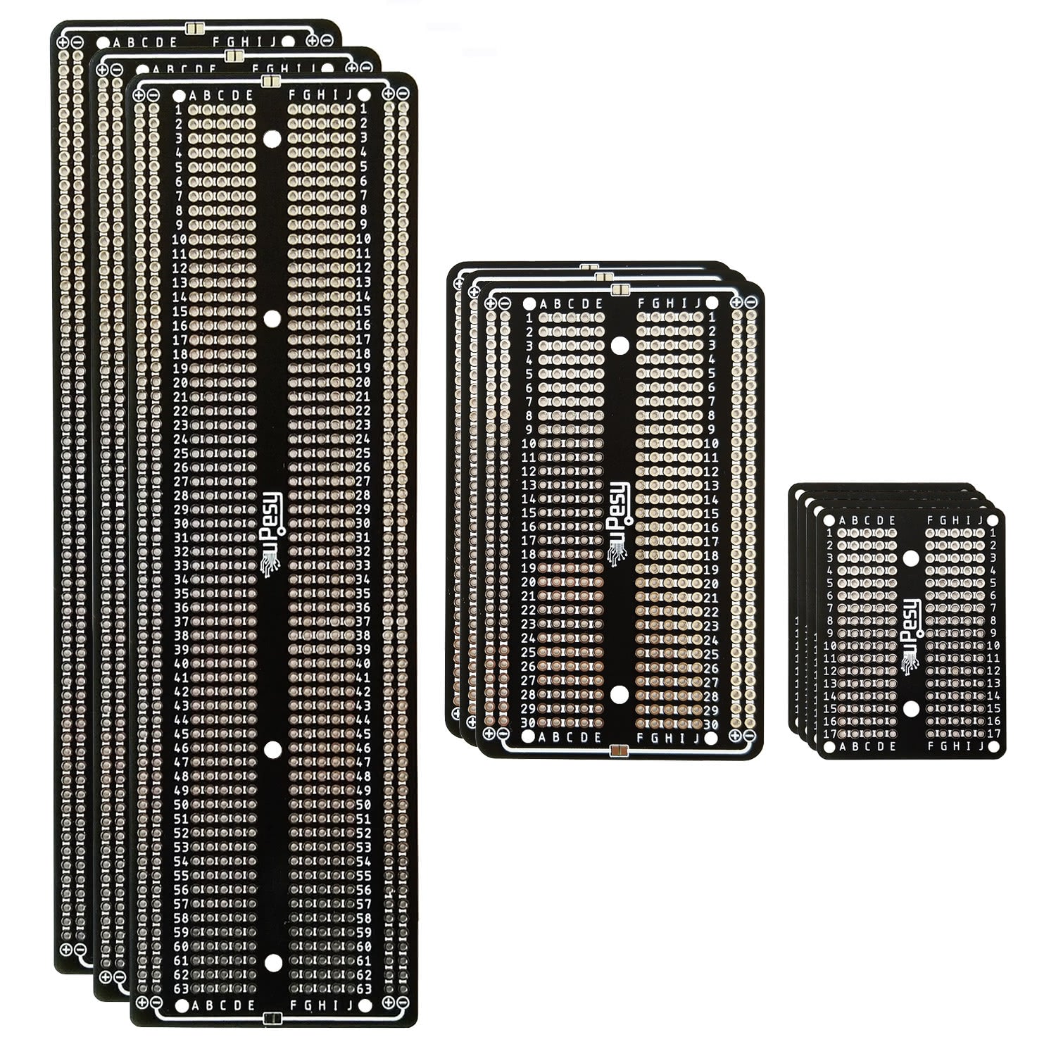
The different sizes
Here are the main characteristics of these prototyping boards:
The
Minivariant corresponds to the size of a Mini breadboard of 170 holes (17 rows) with dimensions: \(51mm \times 38mm \times 1.6 mm\) .The
Mediumvariant corresponds to the size of a 420 holes breadboard (30 rows), i.e., \(87mm \times 53mm \times 1.6 mm\) .The
Largevariant corresponds to the size of a classical breadboard of 800 holes (63 rows), with dimensions: \(171mm \times 53mm \times 1.6 mm\) .
Features
Here are the main features of these prototyping boards:
Pads have a 2.54mm (0.1”) pitch.
Fixing hole of diameter
M2for the smaller ones,M3for the bigger ones. They allow fixing the boards with standoffs (spacers).
1.6mm thick FR4 PCB with pre-tinned pads for easy soldering.
Particular feature: Pads connected in rows
The pads are routed together as follows (the red lines represent the tracks on the board):
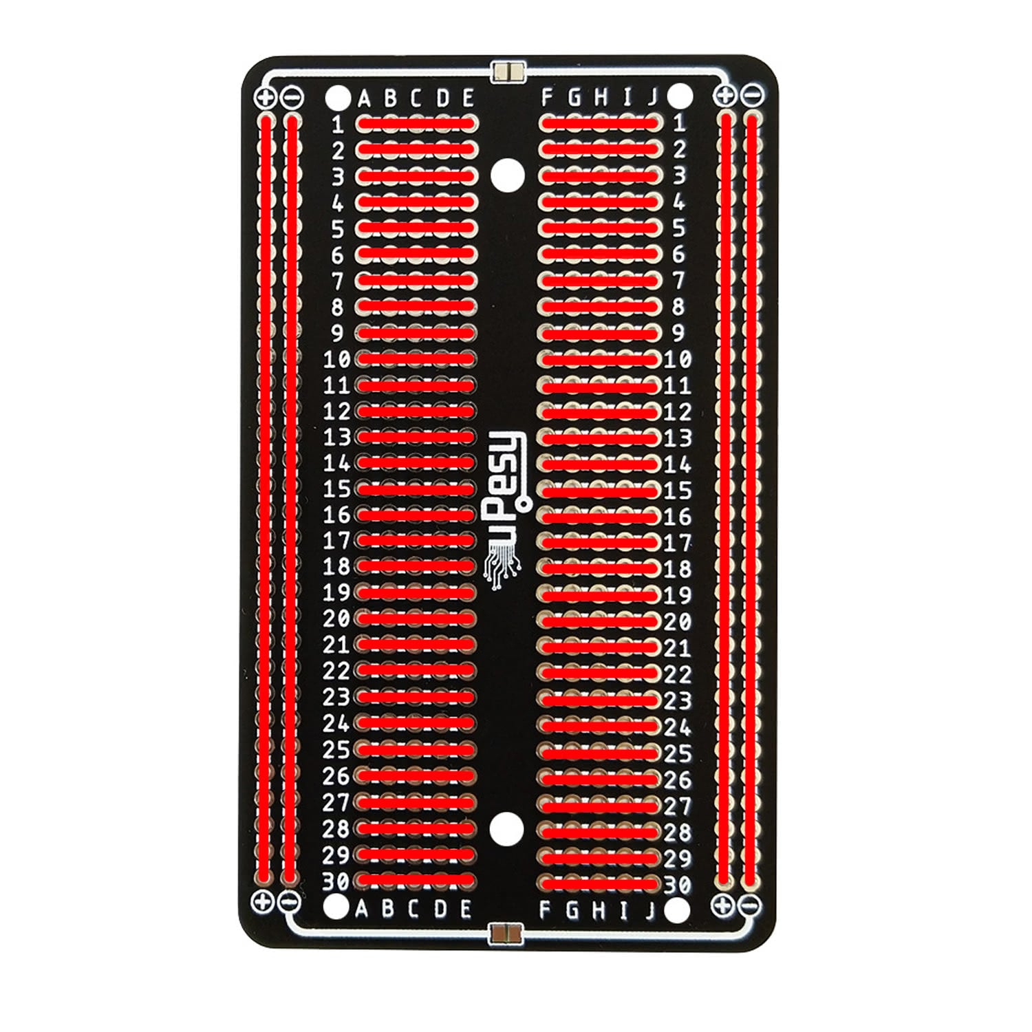
Note
It is the same as on a standard breadboard
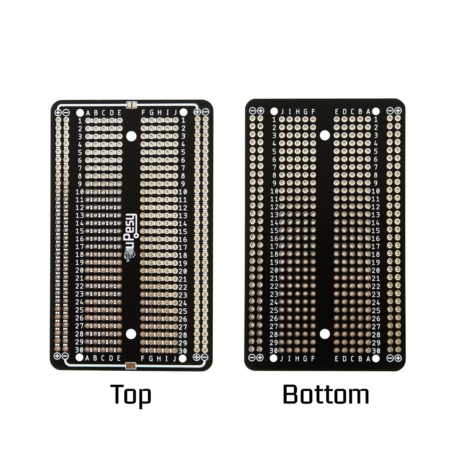
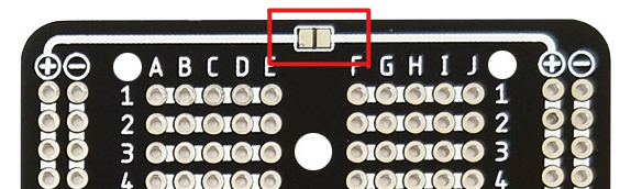
Power tracks
On the Medium and Large variants, power supply tracks on both sides are separated. To have the same power supply, connecting them with a small soldering point at the location provided for this purpose is possible. They are on the top side (the one with the logo).
The bottom one allows to connect of the two ground tracks (
-) :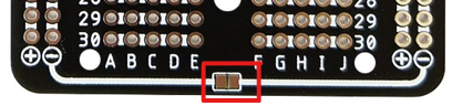
The top one allows you to connect the 2 positive tracks (
+) :
Note
For example, we can connect only the ground and have a 5V supply on the track + on the left and 3.3V on the right.
Usage recommendations
The boards must be used for an electronic circuit supplied with low voltage (<48V DC).
Warning
Do not use with mains voltages of 220V. The distance between the pads is not large enough and the circuit is exposed.